Difference between revisions of "PENNYWHISTLE"
(→Rewrite for final release) |
|||
| Line 1: | Line 1: | ||
| − | + | 16 / 20 Watt RF Power Amplifier | |
| − | PennyWhistle is a compact RF power amplifier | + | [[Image:DCP_3376_(Small).JPG]] |
| + | |||
| + | |||
| + | PennyWhistle 16 to 20 Watt RF PA using Mitsubishi “RD15” VHF Transistors | ||
| + | |||
| + | == INTRODUCTION == | ||
| + | PennyWhistle is a compact RF power amplifier that can be used with Penelope and Alex to make a complete 16 Watt PEP Linear or 20 Watt saturated CW transmitter. This amplifier can quickly and inexpensively be used to get an HPSDR on the air, either barefoot, or as a driver for a larger linear. It covers the same 160 Meter through 6 Meter bands as the rest of HPSDR. | ||
| − | |||
It is 10 cm by 8 cm (half Euro-board size.) | It is 10 cm by 8 cm (half Euro-board size.) | ||
| − | |||
| − | + | == DESCRIPTION == | |
| − | + | The amplifier has a single push-pull output stage that uses a pair of TO-220 “15 Watt” Mitsubishi RD15HVF1 parts, and has approximately 19 dB gain, depending where you bias it, so it will deliver 16 to 20 watts output with one-fourth watt drive. | |
| − | |||
| − | + | I would expect this could be sold as a bare PC build-it-yourself kit. It uses surface mount, but would be easy to build. There are two easily wound transformers and the output transformer is preassembled and wound, from Communications Concepts. As a pure kit, hopefully it could be offered in the same time frame as ALEX, and let people get on the air. | |
| − | + | It will fit in a Euro-Card housing, with an appropriate heat sink., or it can be mounted with a heat sink inside of the Pandora housing. We need to extract about 20 to 25 watts of heat when transmitting continuously. Dissipation in standby is negligible. The circuit is capable of continuous duty, provided that the heatsink is big enough to hold a reasonable temperature. | |
| + | [[Image:System_(Small).JPG]] | ||
| + | |||
| + | |||
| + | Alpha board running with Mercury, Penelope, Alex and Ozy. | ||
[[Image:PW_SCH_Med.jpg]] | [[Image:PW_SCH_Med.jpg]] | ||
| − | + | Schematic | |
| + | |||
| + | The two output transistors are actually mounted underneath the PC board, with their heat sink tabs bolted to the main heatsink. | ||
| + | The PCB is mounted to the main heatsink with ¼ inch long #4-40 spacers at four locations in the vicinity of the PA transistors. The leads from the transistors are bent upwards and through the PCB and soldered from the top. Holes in the PCB allow unbolting the transistors from the main heatsink if needed, without having to unsolder anything. | ||
| − | |||
| − | |||
| − | |||
| − | + | == TEST RESULTS == | |
| + | [[Image:PW_Input_VSWR_(Small).JPG]] | ||
| + | PennyWhistle input VSWR (without input attenuator.) | ||
| − | |||
| − | |||
| + | [[Image:PW_Output_(Medium).JPG]] | ||
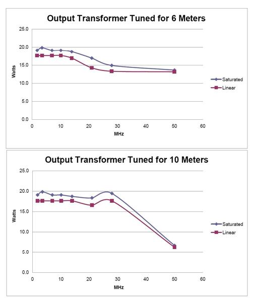
| + | PennyWhistle Output versus frequency | ||
| − | + | == CURRENT STATUS == | |
| − | + | April 19, 2009 | |
| + | Assembly and testing of the Alpha cards is complete, with agreement from the Alpha testers to release the design to TAPR for kitting and distribution. | ||
| + | == RELATED DOCUMENTS AND LINKS == | ||
| − | + | The RF power transistors used in this design are true RF power transistors, although quite inexpensive and | |
| + | packaged in plastic TO-220 packages. By true RF, the metal heat sink tabs on the transistors are at ground | ||
| + | potential, so can be directly attached to the metal heat sink. The transistors are rated for generating | ||
| + | RF power up to 200 MHz. | ||
| − | + | http://www.rfparts.com/pdf_docs/RD/rd15hvf1.pdf | |
| − | |||
| − | + | The PCB cards and schematics are designed in EAGLE Layout Editor | |
| + | |||
| + | http://www.cadsoftusa.com/ | ||
| + | |||
| + | http://www.cadsoft.de/ | ||
Revision as of 08:51, 23 April 2009
16 / 20 Watt RF Power Amplifier
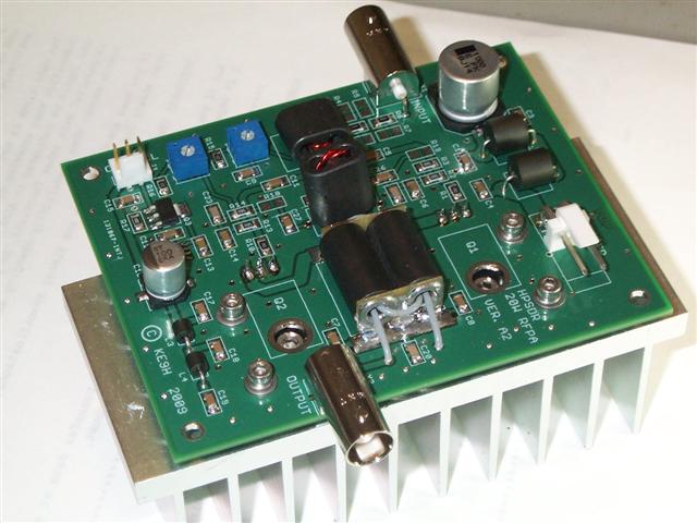
PennyWhistle 16 to 20 Watt RF PA using Mitsubishi “RD15” VHF Transistors
INTRODUCTION
PennyWhistle is a compact RF power amplifier that can be used with Penelope and Alex to make a complete 16 Watt PEP Linear or 20 Watt saturated CW transmitter. This amplifier can quickly and inexpensively be used to get an HPSDR on the air, either barefoot, or as a driver for a larger linear. It covers the same 160 Meter through 6 Meter bands as the rest of HPSDR.
It is 10 cm by 8 cm (half Euro-board size.)
DESCRIPTION
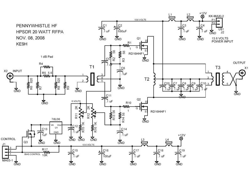
The amplifier has a single push-pull output stage that uses a pair of TO-220 “15 Watt” Mitsubishi RD15HVF1 parts, and has approximately 19 dB gain, depending where you bias it, so it will deliver 16 to 20 watts output with one-fourth watt drive.
I would expect this could be sold as a bare PC build-it-yourself kit. It uses surface mount, but would be easy to build. There are two easily wound transformers and the output transformer is preassembled and wound, from Communications Concepts. As a pure kit, hopefully it could be offered in the same time frame as ALEX, and let people get on the air.
It will fit in a Euro-Card housing, with an appropriate heat sink., or it can be mounted with a heat sink inside of the Pandora housing. We need to extract about 20 to 25 watts of heat when transmitting continuously. Dissipation in standby is negligible. The circuit is capable of continuous duty, provided that the heatsink is big enough to hold a reasonable temperature.
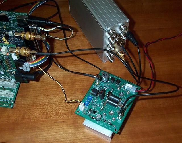
Alpha board running with Mercury, Penelope, Alex and Ozy.
Schematic
The two output transistors are actually mounted underneath the PC board, with their heat sink tabs bolted to the main heatsink.
The PCB is mounted to the main heatsink with ¼ inch long #4-40 spacers at four locations in the vicinity of the PA transistors. The leads from the transistors are bent upwards and through the PCB and soldered from the top. Holes in the PCB allow unbolting the transistors from the main heatsink if needed, without having to unsolder anything.
TEST RESULTS
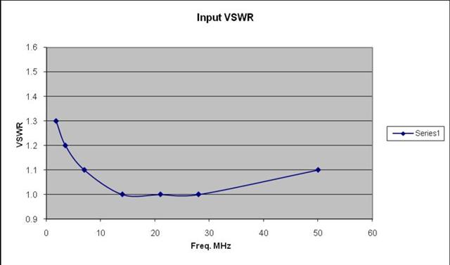
PennyWhistle input VSWR (without input attenuator.)
PennyWhistle Output versus frequency
CURRENT STATUS
April 19, 2009
Assembly and testing of the Alpha cards is complete, with agreement from the Alpha testers to release the design to TAPR for kitting and distribution.
RELATED DOCUMENTS AND LINKS
The RF power transistors used in this design are true RF power transistors, although quite inexpensive and packaged in plastic TO-220 packages. By true RF, the metal heat sink tabs on the transistors are at ground potential, so can be directly attached to the metal heat sink. The transistors are rated for generating RF power up to 200 MHz.
http://www.rfparts.com/pdf_docs/RD/rd15hvf1.pdf
The PCB cards and schematics are designed in EAGLE Layout Editor
