Difference between revisions of "HERMES"
(→Hermes - A DUC/DDC Transceiver: move image up) |
|||
| (70 intermediate revisions by 8 users not shown) | |||
| Line 2: | Line 2: | ||
''' Hermes - A DUC/DDC Transceiver ''' | ''' Hermes - A DUC/DDC Transceiver ''' | ||
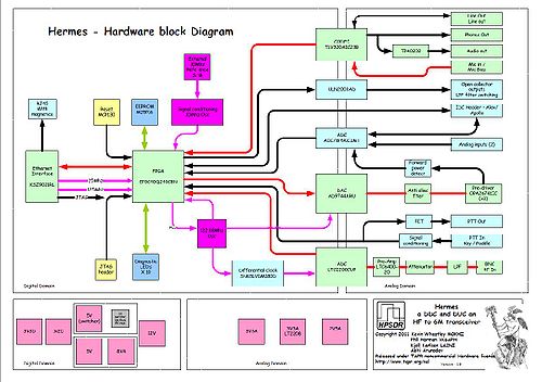
| − | [[Image: | + | [[Image:Hardware_Block_Diagram_1_8.JPG|thumb|500px|Hardware block diagram. Click to enlarge.]] |
Project Leader: Kevin M0KHZ | Project Leader: Kevin M0KHZ | ||
| − | + | ====Update 11 July 2012==== | |
| − | + | Hermes is a single board Digital Up and Down Conversion (DUC/DDC) full duplex HF + 6m multi-mode transceiver. | |
| − | + | It is basically the [[MERCURY|Mercury]], [[PENNYLANE|Pennylane]], [[METIS|Metis]] and [[EXCALIBUR|Excalibur]] (less TCXO) boards rolled into one PCB. The board communicates to an associated PC via 100T/1000T Ethernet. | |
| − | + | Hermes has the following features and facilities: | |
| − | * | + | * Continuous, uninterrupted, receive coverage from 10kHz to 55MHz. |
| − | *Mercury | + | * Supports Real-Time display of entire spectrum from 0-55MHz (with suitable PC software) |
| − | * | + | * Supports 7 fully independent receivers (sharing the same antenna - and with suitable PC software) |
| − | * | + | * Each receiver can display 48/96/192kHz of spectrum |
| − | * | + | * Blocking Dynamic Range (ARRL Method) - no detectable gain compression below ADC overload |
| − | * | + | * High performance receiver – same specifications as the HPSDR Mercury receiver (ie Dynamic Range typically 125dB) |
| − | * | + | * Transmit and receiver image rejection > 110dB |
| − | * | + | * Full duplex operation, any split over entire 160m to 6m range. |
| − | * | + | * Transmitter two-tone 3rd order IMD of -50dBc on 20m @ 400mW output |
| + | * 500mW RF output on 160 – 10m amateur bands, 350mW on 6m | ||
| + | * Built-in high performance preamp, with a noise floor typically -135dBm in 500Hz | ||
| + | * Software-selectable 31dB input attenuator in 1dB steps | ||
| + | * FPGA code can be updated via the Industry Standard TCP/IP network Ethernet connection | ||
| + | * Seven user-configurable open-collector outputs, independently selectable per band and Tx/Rx (for relay control, etc - with sequencing via PC code) | ||
| + | * Separate open-collector PTT connection for amplifier control, etc, with sequencer | ||
| + | * Microphone PTT jumper-selectable from tip or ring connection | ||
| + | * Bias for electret microphones via jumper | ||
| + | * Four user-configurable 12 bit analogue inputs (for ALC, SWR etc) | ||
| + | * Three user-configurable digital inputs (for linear amplifier over temperature, etc) | ||
| + | * Can operate from a 13.8v DC supply or +12v and +5v supplies | ||
| + | * Jumper selected in-built low noise and high efficiency switch mode power supply designed by Kjell Karson,LA2NI – less than 600mA (receive - one receiver) from a 13.8V supply | ||
| + | * I2C bus connector for control of external equipment | ||
| + | * Full QSK operation (performance dependant on associated PC and control software) | ||
| + | * Low-level transmitter output for transverter use via user-selectable output attenuator | ||
| + | * Stereo audio outputs at line and headphone levels | ||
| + | * In-built 1W stereo audio amplifier for directly driving speakers | ||
| + | * Direct, de-bounced connections for a Morse key (straight or iambic) and PTT | ||
| + | * Low phase noise (-140dBc/Hz @ 1kHz at 14MHz) 122.88MHz master clock,which can be phase-locked to an internal 10MHz TCXO or external frequency reference | ||
| + | * Direct ribbon cable interface to [[Apollo]] 15W power amplifier, low pass filters and automatic ATU or ANAN-10 10W power amplifier and low power filters [http://www.apache-labs.com http://www.apache-labs.com] | ||
| + | * Industry Standard TCP/IP network Ethernet interface supports static, APIPA or DHCP IP address | ||
| + | * Hermes responds to ping and ARP requests and auto senses network connection speed | ||
| + | * PCB is 160mm x 120mm, 8 layers | ||
| − | |||
| − | |||
| − | |||
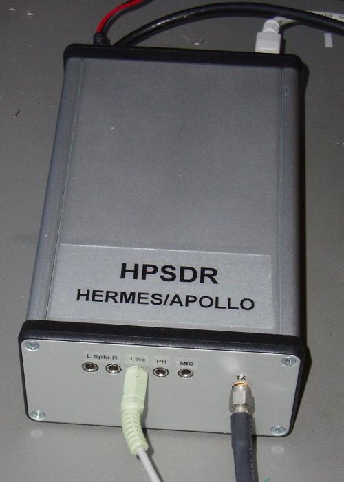
| − | + | [[Apollo]] is a combined 15w PA, Low Pass Filter bank and Automatic ATU. The Apollo project is led by Kjell Karlsen LA2NI. | |
| + | |||
| − | + | Hermes can be used as a Vector Network Analyzer: [[VNA]] | |
| − | + | [[Image:hermesapolloincase.jpg|thumb|500px|Hermes and Apollo in enclosure - photo copyright Kjell Karlsen 2010.]] | |
| − | |||
| − | |||
| − | |||
| − | |||
| − | |||
| − | |||
| − | |||
| − | |||
| − | |||
| − | |||
| − | |||
| − | |||
| − | |||
| − | |||
| − | + | ====Update 7 August 2011==== | |
| − | + | The primary PCB layout team member of Hermes, Abhi has a blog on Hermes at [http://hpsdrhermes.blogspot.com/ http://hpsdrhermes.blogspot.com/ ]. --[[User:KV0S|KV0S, Dave]] | |
| − | + | ||
| − | + | ||
| − | + | ||
| − | + | ||
| − | + | ||
| − | + | ||
| − | + | ====Update 7 July 2011==== | |
| − | + | A prototype board has been built and tested. The board is fully functional and meets or exceeds the performance of the Mercury/Penelope/Metis/Excalibur boards the design is based on. | |
| − | + | Some minor board layout issues are currently being addressed and a pre-production layout is presently being prepared. | |
| + | The KD5TFD and W5WC versions of PowerSDR(TM) as well as KISS Konsole have been modified to provide native Hermes support. | ||
| − | + | Ken, N9VV, has a lot of information regarding Hermes on his web site here http://www.n9vv.com/hamradio.html | |
| − | + | [[Image:Hermes.jpg|thumb|500px|center| (click for larger image) photo courtesy Abhi Arunoday ]] | |
| + | There are also the [[Hermes Board Build Notes]] | ||
| − | + | ====Update 2 December 2012==== | |
| − | + | A useful website for Hermes users can be found at [http://www.k9ivb.net/hermes/ www.k9ivb.net/hermes/] by Dick K9IVB. --[[User:KV0S|KV0S, Dave]] | |
| − | + | There are the [[Hermes Board Build Notes]] as well. | |
| − | + | [[Category:Hermes| ]] | |
| − | + | ||
| − | + | ||
| − | + | ||
| − | + | ||
| − | + | ||
| − | + | ||
| − | + | ||
| − | + | ||
Latest revision as of 05:50, 28 December 2012
Hermes - A DUC/DDC Transceiver
Project Leader: Kevin M0KHZ
Update 11 July 2012
Hermes is a single board Digital Up and Down Conversion (DUC/DDC) full duplex HF + 6m multi-mode transceiver.
It is basically the Mercury, Pennylane, Metis and Excalibur (less TCXO) boards rolled into one PCB. The board communicates to an associated PC via 100T/1000T Ethernet.
Hermes has the following features and facilities:
- Continuous, uninterrupted, receive coverage from 10kHz to 55MHz.
- Supports Real-Time display of entire spectrum from 0-55MHz (with suitable PC software)
- Supports 7 fully independent receivers (sharing the same antenna - and with suitable PC software)
- Each receiver can display 48/96/192kHz of spectrum
- Blocking Dynamic Range (ARRL Method) - no detectable gain compression below ADC overload
- High performance receiver – same specifications as the HPSDR Mercury receiver (ie Dynamic Range typically 125dB)
- Transmit and receiver image rejection > 110dB
- Full duplex operation, any split over entire 160m to 6m range.
- Transmitter two-tone 3rd order IMD of -50dBc on 20m @ 400mW output
- 500mW RF output on 160 – 10m amateur bands, 350mW on 6m
- Built-in high performance preamp, with a noise floor typically -135dBm in 500Hz
- Software-selectable 31dB input attenuator in 1dB steps
- FPGA code can be updated via the Industry Standard TCP/IP network Ethernet connection
- Seven user-configurable open-collector outputs, independently selectable per band and Tx/Rx (for relay control, etc - with sequencing via PC code)
- Separate open-collector PTT connection for amplifier control, etc, with sequencer
- Microphone PTT jumper-selectable from tip or ring connection
- Bias for electret microphones via jumper
- Four user-configurable 12 bit analogue inputs (for ALC, SWR etc)
- Three user-configurable digital inputs (for linear amplifier over temperature, etc)
- Can operate from a 13.8v DC supply or +12v and +5v supplies
- Jumper selected in-built low noise and high efficiency switch mode power supply designed by Kjell Karson,LA2NI – less than 600mA (receive - one receiver) from a 13.8V supply
- I2C bus connector for control of external equipment
- Full QSK operation (performance dependant on associated PC and control software)
- Low-level transmitter output for transverter use via user-selectable output attenuator
- Stereo audio outputs at line and headphone levels
- In-built 1W stereo audio amplifier for directly driving speakers
- Direct, de-bounced connections for a Morse key (straight or iambic) and PTT
- Low phase noise (-140dBc/Hz @ 1kHz at 14MHz) 122.88MHz master clock,which can be phase-locked to an internal 10MHz TCXO or external frequency reference
- Direct ribbon cable interface to Apollo 15W power amplifier, low pass filters and automatic ATU or ANAN-10 10W power amplifier and low power filters http://www.apache-labs.com
- Industry Standard TCP/IP network Ethernet interface supports static, APIPA or DHCP IP address
- Hermes responds to ping and ARP requests and auto senses network connection speed
- PCB is 160mm x 120mm, 8 layers
Apollo is a combined 15w PA, Low Pass Filter bank and Automatic ATU. The Apollo project is led by Kjell Karlsen LA2NI.
Hermes can be used as a Vector Network Analyzer: VNA
Update 7 August 2011
The primary PCB layout team member of Hermes, Abhi has a blog on Hermes at http://hpsdrhermes.blogspot.com/ . --KV0S, Dave
Update 7 July 2011
A prototype board has been built and tested. The board is fully functional and meets or exceeds the performance of the Mercury/Penelope/Metis/Excalibur boards the design is based on.
Some minor board layout issues are currently being addressed and a pre-production layout is presently being prepared. The KD5TFD and W5WC versions of PowerSDR(TM) as well as KISS Konsole have been modified to provide native Hermes support.
Ken, N9VV, has a lot of information regarding Hermes on his web site here http://www.n9vv.com/hamradio.html
There are also the Hermes Board Build Notes
Update 2 December 2012
A useful website for Hermes users can be found at www.k9ivb.net/hermes/ by Dick K9IVB. --KV0S, Dave
There are the Hermes Board Build Notes as well.


