Difference between revisions of "VNA"
(→Update 14 August 2012) |
m (→Vector Network Analyser: link corr) |
||
| (6 intermediate revisions by 2 users not shown) | |||
| Line 1: | Line 1: | ||
==Vector Network Analyser== | ==Vector Network Analyser== | ||
| − | This project is to develop PC and FPGA software in order to use Hermes (and possibly Mercury, PennyLane and Metis) as a Vector Network Analyser. | + | This project is to develop PC and FPGA software in order to use [[Hermes]] (and possibly [[Mercury]], [[PennyLane]] and [[Metis]]) as a [http://en.wikipedia.org/wiki/Network_analyzer_%28electrical%29 Vector Network Analyser]. |
Project Leader: Phil VK6APH | Project Leader: Phil VK6APH | ||
| Line 21: | Line 21: | ||
| − | [[Image: | + | [[Image:HermesVNA.png|200px|thumb|VNA Screen Shot.]] |
| + | |||
| + | |||
| + | |||
====Reflection Bridge==== | ====Reflection Bridge==== | ||
| Line 35: | Line 38: | ||
The ferrite beads are Steward LFB090050-000, which seem to match Digikey part number 240-2135-ND, listed as a product of Laird-Signal Integrity Products. | The ferrite beads are Steward LFB090050-000, which seem to match Digikey part number 240-2135-ND, listed as a product of Laird-Signal Integrity Products. | ||
| + | |||
| + | [[Category:Vector network analyzer| ]] | ||
Latest revision as of 12:34, 28 December 2012
Vector Network Analyser
This project is to develop PC and FPGA software in order to use Hermes (and possibly Mercury, PennyLane and Metis) as a Vector Network Analyser.
Project Leader: Phil VK6APH
Update 14 August 2012
FPGA code for Hermes has been developed and tested that enables the transmitter (which will be used as the VNA signal source) and receiver in Hermes to be phase synchronous.
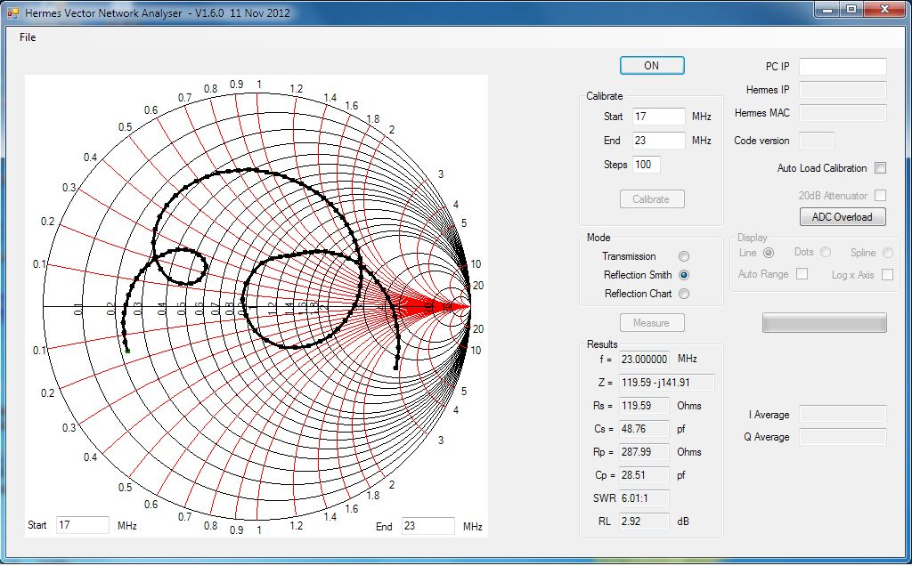
PC code has been written (in C# using the free Visual Studio 2010 software) to implement the Reflection function of a VNA. The code draws a Smith Chart, which is zoomable, and displays the Impedance being measured as a complex value on the chart. Additionally, the equivalent series and parallel impedance is displayed as are the equivalent component values at the measurement frequency. The VSWR and Return Loss are also displayed.
The code enables Open/Short/Load calibration to be made (presently at a single frequency); the calibration data can be saved to a file and subsequently re-loaded as required. The repeatability of measurements after loading the previous calibration data is excellent.
The screen shot shows the current status of the PC software. An number of items being displayed are for debug purposes only and will be removed when no longer required.
The additional code required in the Hermes FPGA is very small. In which case a future version of code will include the ability to use Hermes in VNA mode via a Command & Control flag.
Reflection Bridge
Reflection measurements require the use of a directional coupler or reflection bridge. There are a number of different designs, but one that is currently being looked at is a design by Sam Wetterlin. It uses a MiniCircuits balun transformer augmented by a string of three ferrite beads.
PDF showing Sam's design and characterization
The transformer is MiniCircuits TC1-1-13. There are several variants. Is there any advantage to any specific one? The following link leads to a page listing MiniCircuits' "configuration G" (ie balun) transformers.
Configuration G balun transformers
The ferrite beads are Steward LFB090050-000, which seem to match Digikey part number 240-2135-ND, listed as a product of Laird-Signal Integrity Products.

