Difference between revisions of "LPU"
(wiki) |
|||
| (31 intermediate revisions by 6 users not shown) | |||
| Line 1: | Line 1: | ||
| − | [[Image: | + | [[Image:LPU_TOP_sm.JPG|200px|thumb|left|LPU Prototype]] |
''' | ''' | ||
| − | == LPU - HPSDR | + | == Linear Power Unit (LPU) - HPSDR Simple Power Supply == |
''' | ''' | ||
Project Leader: Scotty WA2DFI | Project Leader: Scotty WA2DFI | ||
| − | "LPU" is the project-name for a simple HPSDR power supply. Although power supplies are widely available, | + | '''"LPU"''' is the project-name for a simple HPSDR power supply. Although power supplies are widely available, the LPU will provide a convenient low-noise solution until the more complex [[Demeter]] power supply is completed. The LPU (as well as Demeter) are specifically designed for the HPSDR project. With the approaching release of Mercury, this is the last hardware part of a basic functional HPSDR transceiver. |
| − | + | The LPU will not take the place of Demeter; it is intended as an interim solution to power HPSDR boards until Demeter is completed. | |
| − | + | Further information will be presented on this page as it becomes available. | |
| − | + | 73, | |
| + | Scotty WA2DFI | ||
| + | |||
| + | '''Updated: (26th December 2008):''' | ||
| + | |||
| + | All 5 LPU prototypes assembled and tested. Added pictures. Updated schematic to XA4, which matches the prototype PCBs. Except for the capacitors in parallel with C3 and C7, it is accurate for a functional unit. | ||
| + | |||
| + | [[Image:LPU_BOT_sm.JPG|200px|thumb|left|LPU Bottom View]] | ||
| + | [[Image:LPU_Merc_Ozy_Atlas_sm.JPG|200px|thumb|left|LPU in [[ATLAS Atlas]] backplane with Mercury and Ozy]] | ||
| + | |||
| + | '''Updated: (18th December 2008):''' | ||
| + | |||
| + | First LPU PCB assembled. +5V and +3.3V regulator outputs oscillate. Added additional capacitance to each output by adding 47uF 10V tantalum capacitors in parallel with C3 and C7. Outputs now stable. | ||
| + | |||
| + | '''Updated: (17th December 2008):''' | ||
| + | |||
| + | Received prototype PCBs. Parts previously ordered and all in stock. Many thanks to Lyle, KK7P for doing the PCB layout and edits. | ||
| + | |||
| + | '''Updated: (30th October 2008):''' | ||
| + | |||
| + | '''1 Physical''' | ||
| + | |||
| + | The LPU (Linear Power Unit) is a self-contained power supply board for HPSDR. It is mounted onto a 20-pin ATX connector that mates with the connector on the [[ATLAS|Atlas]] board. | ||
| + | |||
| + | '''2 Requirements''' | ||
| + | |||
| + | HPSDR boards require power outlined in the following table. | ||
| + | |||
| + | [[Image:Table1.png]] | ||
| + | |||
| + | '''3 Electrical''' | ||
| + | |||
| + | The LPU accepts a 12VDC regulated input and produced the following outputs: | ||
| + | |||
| + | [[Image:Table2.png]] | ||
| + | |||
| + | The LPU does not produce -5V or any standby voltages. It ignores the ATX power-on signal and | ||
| + | is always on. There is a jumper to shut off the -12V switching regulator when it is not needed in | ||
| + | order to eliminate RF noise. | ||
| + | |||
| + | '''4 LPU Feature List''' | ||
| + | |||
| + | * Input power: 12.5V – 14.5V regulated DC input | ||
| + | * Outputs: +12V@2A, +5V@2A, +3.3V@2A (opt), -12V@100mA | ||
| + | * Poly fuse on each regulator input: +12, +5, +3.3V (opt), -12V regulators | ||
| + | * Plugs into Atlas backplane ATX connector | ||
| + | * Mounting holes allow direct mounting to Atlas backplane | ||
| + | * Strap disable for -12V to reduce noise | ||
| + | * Dual power-pole input connector | ||
| + | * Internal dual power-pole output connector for PA or accessories | ||
| + | * Estimated PCB size: (LxWxH): 119mm X 44mm X 40mm | ||
| + | * Estimated overall size: (LxWxH): 137mm X 54mmX 60mm | ||
| + | |||
| + | Schematic: [[Media:LPU_XA4.pdf]] | ||
| + | |||
| + | [[Category:Hardware available]] | ||
Latest revision as of 12:09, 25 January 2010
Linear Power Unit (LPU) - HPSDR Simple Power Supply
Project Leader: Scotty WA2DFI
"LPU" is the project-name for a simple HPSDR power supply. Although power supplies are widely available, the LPU will provide a convenient low-noise solution until the more complex Demeter power supply is completed. The LPU (as well as Demeter) are specifically designed for the HPSDR project. With the approaching release of Mercury, this is the last hardware part of a basic functional HPSDR transceiver.
The LPU will not take the place of Demeter; it is intended as an interim solution to power HPSDR boards until Demeter is completed.
Further information will be presented on this page as it becomes available.
73, Scotty WA2DFI
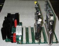
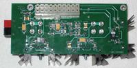
Updated: (26th December 2008):
All 5 LPU prototypes assembled and tested. Added pictures. Updated schematic to XA4, which matches the prototype PCBs. Except for the capacitors in parallel with C3 and C7, it is accurate for a functional unit.

Updated: (18th December 2008):
First LPU PCB assembled. +5V and +3.3V regulator outputs oscillate. Added additional capacitance to each output by adding 47uF 10V tantalum capacitors in parallel with C3 and C7. Outputs now stable.
Updated: (17th December 2008):
Received prototype PCBs. Parts previously ordered and all in stock. Many thanks to Lyle, KK7P for doing the PCB layout and edits.
Updated: (30th October 2008):
1 Physical
The LPU (Linear Power Unit) is a self-contained power supply board for HPSDR. It is mounted onto a 20-pin ATX connector that mates with the connector on the Atlas board.
2 Requirements
HPSDR boards require power outlined in the following table.
3 Electrical
The LPU accepts a 12VDC regulated input and produced the following outputs:
The LPU does not produce -5V or any standby voltages. It ignores the ATX power-on signal and is always on. There is a jumper to shut off the -12V switching regulator when it is not needed in order to eliminate RF noise.
4 LPU Feature List
- Input power: 12.5V – 14.5V regulated DC input
- Outputs: +12V@2A, +5V@2A, +3.3V@2A (opt), -12V@100mA
- Poly fuse on each regulator input: +12, +5, +3.3V (opt), -12V regulators
- Plugs into Atlas backplane ATX connector
- Mounting holes allow direct mounting to Atlas backplane
- Strap disable for -12V to reduce noise
- Dual power-pole input connector
- Internal dual power-pole output connector for PA or accessories
- Estimated PCB size: (LxWxH): 119mm X 44mm X 40mm
- Estimated overall size: (LxWxH): 137mm X 54mmX 60mm
Schematic: Media:LPU_XA4.pdf


