Difference between revisions of "HERCULES"
(added Note #2) |
(Added notes #3 & 4) |
||
| Line 90: | Line 90: | ||
16. Solder and close trim L-1 to L12, L-17 and L-18. | 16. Solder and close trim L-1 to L12, L-17 and L-18. | ||
| + | |||
| + | Note #3 When the assembling of the printed circuit board on the radiator box the same is to be considered as with the disassembly only in reverse order. The radiator box surface must be freely of foreign parts, in particular under the power transistors. Otherwise the heat dissipation is handicapped. A view laterally by the gap between printed circuit board and radiator box is helpful to determine over whether the power transistors flat mounts. It may not be visible a light gap. When finally last screwing on thermal compound can (in thin layer!!) the heat coupling of the power transistors improve. This is meaningful however only for the final stage transistors. | ||
17. Clean off any solder flux left on the circuit board from steps 15 and 16 above and inspect work so far. | 17. Clean off any solder flux left on the circuit board from steps 15 and 16 above and inspect work so far. | ||
| + | |||
18. Apply thermal compound (example: Antec Formula 5... Silver Bullet) to the heat sink surfaces of the transistors (4). Do not apply the compound to the two transistors that mount to the insulating pads. | 18. Apply thermal compound (example: Antec Formula 5... Silver Bullet) to the heat sink surfaces of the transistors (4). Do not apply the compound to the two transistors that mount to the insulating pads. | ||
| + | |||
| + | Note #4 When screwing the fixing bolts in an alternating can solve short release around a half revolution the blocking of the mother on the radiator box and make then further screwing in possible. Also holding of the printed circuit board down against the mother can be helpful. The 8 transistor fixing bolts are screwed in only last and tightened firmly however moderately and evenly. | ||
19. Mate the circuit board to the heatsink and tighten all screws including the hardware from plastic bag in the parts kit. | 19. Mate the circuit board to the heatsink and tighten all screws including the hardware from plastic bag in the parts kit. | ||
Revision as of 13:42, 24 February 2010
HERCULES
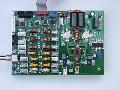
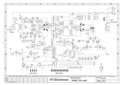
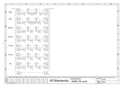
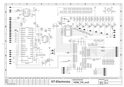
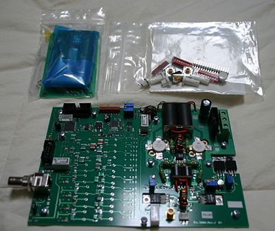
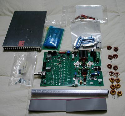
This amplifier is designed to work with the current HPSDR Penelope transmitter assembly to amplify the signal of max. 500 mW to 100 Watts RF output. It was designed to operate from 160m up to and including 6m in all HF Amateur bands in all modes. See Photos 2, 3, & 4 for as built schematic drawings.
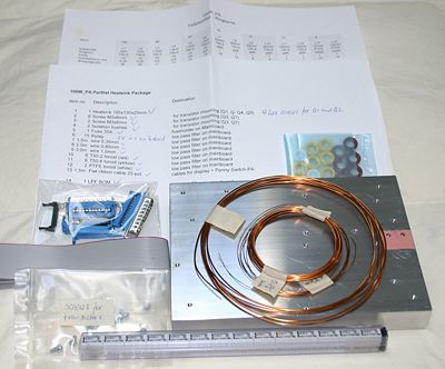
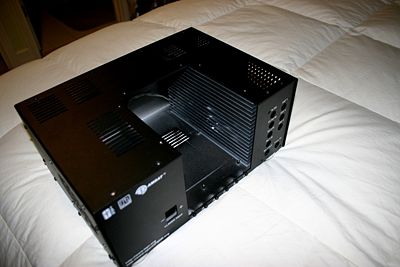
All parts are included including a drilled and tapped 185 X130 X 25 mm heatsink (see photo above). The parts are mailed in two packages. The first package has the heatsink, hardware, toroids, wire, fuse, flat ribbon cable, ribbon connectors, and relays. An overall enclosure is not included.
Functions and Features:
The amplifier uses a four layer circuit board, which makes possible optimum impedance match of all the HF circuit board lines. The Amplifier is installed onto an Aluminum heat sink by the user. Dimensions LxWxH are185 x 130 x 50mm. Cooling fans may be required by the user depending upon type of mounting and the planned duty cycle of usage. Connections to the optional PWR/SWR meter and the HPSDR Pentelope transmit exciter board starts on the Amplifier's printed circuit board via a single flat strip cable. By programming the on board CPLD, additional interfaces can be implemented.
Operating voltages are 12-14 Volts with current input to a maximum of 25 Amperes, HF-power output is 100W PEP on 160-10m, and 50W on 6m.
Frequency range: 1.8MHz to 52MHz with 7 bandpass filters for 160m, 80m, 60/40m, 30/20m, 17/15m, 12/10m and 6m. Designed for max. transmission and min. return, the band pass filters use single-aperture cores and SMD mica capacitors with high Q and min. losses. The bandpass filters can alternatively be used only in the transmit mode or in the transmission and receive mode. The selection takes place via selection of a CPLD program by means of a circuit board jumper.
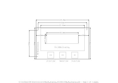
Monitoring of the operational data is accomplished by using an Atmega CONTROLLER and the data is indicated on an optional 4 parameter LCD. The selection of limit values and selection of the display mode take place via 3 keys under the display as follows:
• Temperature measurement at the heat sink to the nearest degree C
• Set point for the start-up of cooling fans is adjustable from 50 to 80°C
• Set points for the limits for switch off the amplifier is adjustable from 60 to 90°C
• Fan Hysteresis is 10°C (in firmware).
• Indicator for power input 0-25A.
• Current limit for switching off Amplifier adjustable from 7 to 25A
• FWD_PWR measurement in Watts
• REV_PWR measurement in Watts
• SWR measurement to one right-of-comma position.
• Limit for switching the final stage off adjustable with SWR greater than 1,5 to 3
Hercules Build Instructions:
Note #1 Leave all screws and nuts installed loosely on the main circuit board as they are. The nuts will be used as circuit board spacers when assembled to the heatsink.
Note #2 After the winding the filter single-aperture cores, they should be checked against the specified inductances, if a L-measuring instrument is present. Inductance can be changed by pushing together or even distributing on the single-aperture cores around approx. 10%. In the case of doubt indicated inductances are valid before the numbers of turns. The wire provided is not solderable, i.e. it must be stripped. It should be stripped up to the single-aperture core, so that the wires can be soldered briefly.
1. Wind 28 turns of .35 mm dia. enameled wire on to a (red) T50-2 toroid. Cut and tin the leads at about 1/2" below the toroid. This coil will be designated L1 at 4 UH.
2. Wind 28 turns of .35 mm dia. enameled wire on to a (red) T50-2 toroid. Cut and tin the leads at about 1/2" below the toroid. This coil will be designated L2 at 4 UH.
3. Wind 17 turns of .8 mm dia. enameled wire on to a (red) T50-2 toroid. Cut and tin the leads at about 1/2" below the toroid. This coil will be designated L3 at 1.5 UH.
4. Wind 19 turns of .8 mm dia. enameled wire on to a (red) T50-2 toroid. Cut and tin the leads at about 1/2" below the toroid. This coil will be designated L4 at 1.8 UH.
5. Wind 15 turns of .8 mm dia. enameled wire on to a (red) T50-2 toroid. Cut and tin the leads at about 1/2" below the toroid. This coil will be designated L5 at 1.2 UH.
6. Wind 15 turns of .8 mm dia. enameled wire on to a (red) T50-2 toroid. Cut and tin the leads at about 1/2" below the toroid. This coil will be designated L6 at 1.3 UH.
7. Wind 10 turns of 1.0 mm dia. enameled wire on to a (yellow) T50-6 toroid. Cut and tin the leads at about 1/2" below the toroid. This coil will be designated L7 at 620 nH.
8. Wind 10 turns of 1.0 mm dia. enameled wire on to a (yellow) T50-6 toroid. Cut and tin the leads at about 1/2" below the toroid. This coil will be designated L8 at 620 nH.
9. Wind 9 turns of 1.0 mm dia. enameled wire on to a (yellow) T50-6 toroid. Cut and tin the leads at about 1/2" below the toroid. This coil will be designated L9 at 430 nH.
10. Wind 9 turns of 1.0 mm dia. enameled wire on to a (yellow) T50-6 toroid. Cut and tin the leads at about 1/2" below the toroid. This coil will be designated L10 at 430 nH.
11. Wind 7 turns of 1.0 mm dia. enameled wire on to a (yellow) T50-6 toroid. Cut and tin the leads at about 1/2" below the toroid. This coil will be designated L11 at 300 nH.
12. Wind 7 turns of 1.0 mm dia. enameled wire on to a (yellow) T50-6 toroid. Cut and tin the leads at about 1/2" below the toroid. This coil will be designated L12 at 300 nH.
13. Wind 10 turns of 1.0 mm dia. enameled wire on to a (white) PTFE toroid. Cut and tin the leads at about 1/2" below the toroid. This coil will be designated L17 at 137 nH.
14. Wind 10 turns of 1.0 mm dia. enameled wire on to a (white) PTFE toroid. Cut and tin the leads at about 1/2" below the toroid. This coil will be designated L18 at 143 nH.
15. Solder the 14 remaining relays to the main circuit board.
16. Solder and close trim L-1 to L12, L-17 and L-18.
Note #3 When the assembling of the printed circuit board on the radiator box the same is to be considered as with the disassembly only in reverse order. The radiator box surface must be freely of foreign parts, in particular under the power transistors. Otherwise the heat dissipation is handicapped. A view laterally by the gap between printed circuit board and radiator box is helpful to determine over whether the power transistors flat mounts. It may not be visible a light gap. When finally last screwing on thermal compound can (in thin layer!!) the heat coupling of the power transistors improve. This is meaningful however only for the final stage transistors.
17. Clean off any solder flux left on the circuit board from steps 15 and 16 above and inspect work so far.
18. Apply thermal compound (example: Antec Formula 5... Silver Bullet) to the heat sink surfaces of the transistors (4). Do not apply the compound to the two transistors that mount to the insulating pads.
Note #4 When screwing the fixing bolts in an alternating can solve short release around a half revolution the blocking of the mother on the radiator box and make then further screwing in possible. Also holding of the printed circuit board down against the mother can be helpful. The 8 transistor fixing bolts are screwed in only last and tightened firmly however moderately and evenly.
19. Mate the circuit board to the heatsink and tighten all screws including the hardware from plastic bag in the parts kit.
