Difference between revisions of "Instruments required"
(+cat) |
m (spelling) |
||
| Line 1: | Line 1: | ||
| − | #Two (3) Signal generators | + | # Two (3) Signal generators |
| − | # | + | # Hybrid combiner |
| − | #Audio AC voltmeter | + | # Audio AC voltmeter |
| − | #Distortion meter (FM Only) | + | # Distortion meter (FM Only) |
| − | #Noise figure meter (for noise figure measurements only) | + | # Noise figure meter (for noise figure measurements only) |
| − | #Two (2) step attenuators with 10dB and 1dB steps | + | # Two (2) step attenuators with 10dB and 1dB steps |
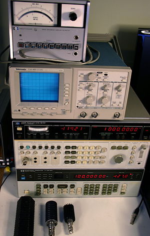
[[Image:W9KFBinstrumentstack.jpg|thumb|300px|Top to bottom, HP 3406A Broadband Sampling voltmeter, Tektronics TAS 465 Two Channel 100MHz Oscilloscope, HP 3586B Selective Level Meter, and HP 8656B Signal Generator]] | [[Image:W9KFBinstrumentstack.jpg|thumb|300px|Top to bottom, HP 3406A Broadband Sampling voltmeter, Tektronics TAS 465 Two Channel 100MHz Oscilloscope, HP 3586B Selective Level Meter, and HP 8656B Signal Generator]] | ||
The signal generators at the W9KFB lab are as follows: | The signal generators at the W9KFB lab are as follows: | ||
| − | #HP 3586B Selective Level Meter (dBm measurements are calibrated for 75 Ohm characteristic impedance, signal is 0 dBm out only at the level measurement frequency) | + | # HP 3586B Selective Level Meter (dBm measurements are calibrated for 75 Ohm characteristic impedance, signal is 0 dBm out only at the level measurement frequency) |
| − | #HP 8656B Signal Generator 0.1-990 MHz (dBm measurements are calibrated for 50 Ohm characteristic impedance) | + | # HP 8656B Signal Generator 0.1-990 MHz (dBm measurements are calibrated for 50 Ohm characteristic impedance) |
| − | #HP 10544A Crystal Oscillator | + | # HP 10544A Crystal Oscillator |
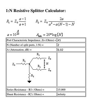
[[Image:45 Ohm combiner.jpg|thumb|300px|Formulas and Values for a 45 Ohm Hybrid Combiner]] | [[Image:45 Ohm combiner.jpg|thumb|300px|Formulas and Values for a 45 Ohm Hybrid Combiner]] | ||
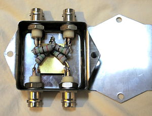
[[Image:Homebrewcombiner.jpg|thumb|300px|Homebrew 45 Ohm Hybrid Combiner]] | [[Image:Homebrewcombiner.jpg|thumb|300px|Homebrew 45 Ohm Hybrid Combiner]] | ||
| − | The | + | The Hybrid combiner was made from an old PC network splitter. The device was found in an used PC warehouse. It was a four port device with 4 BNC jacks on it. On inspection of the device, we found that it was a resistive splitter with four 39 Ohm resistors connected to each BNC center contact and a common point. These were removed and replaced with 15 Ohm 2 Watt 2% resistors metal film resistors (NTE 2W015 Flameproof Resistors). |
To design you own splitter/combiner see this web site for a calculator[http://www.mantaro.com/resources/impedance_calculator.htm#one_to_n_resistive_splitter] | To design you own splitter/combiner see this web site for a calculator[http://www.mantaro.com/resources/impedance_calculator.htm#one_to_n_resistive_splitter] | ||
Latest revision as of 02:23, 24 April 2011
- Two (3) Signal generators
- Hybrid combiner
- Audio AC voltmeter
- Distortion meter (FM Only)
- Noise figure meter (for noise figure measurements only)
- Two (2) step attenuators with 10dB and 1dB steps
The signal generators at the W9KFB lab are as follows:
- HP 3586B Selective Level Meter (dBm measurements are calibrated for 75 Ohm characteristic impedance, signal is 0 dBm out only at the level measurement frequency)
- HP 8656B Signal Generator 0.1-990 MHz (dBm measurements are calibrated for 50 Ohm characteristic impedance)
- HP 10544A Crystal Oscillator
The Hybrid combiner was made from an old PC network splitter. The device was found in an used PC warehouse. It was a four port device with 4 BNC jacks on it. On inspection of the device, we found that it was a resistive splitter with four 39 Ohm resistors connected to each BNC center contact and a common point. These were removed and replaced with 15 Ohm 2 Watt 2% resistors metal film resistors (NTE 2W015 Flameproof Resistors).
To design you own splitter/combiner see this web site for a calculator[1]
Several hams are considering using the new Excalibur board as a test oscillator for SSB Phase Noise measurement. 10 MHz is not the best frequency to use, but the TCXO frequency can be changed to 16 MHz by purchasing a new one. John, N8UR, has done a detailed Allan Variance and phase noise measurement of the TCXO on Excalibur. View his measurement results on this website at:this site. Thanks to John for his testing, and taking time to post the results.
We have found inexpensive used cell-tower 4.800000 MHz OCXOs on eBay recently. They require 12 Volt power and output is +15 dBm. We will test them and evaluate their application as a low phase noise test oscillator.


