Difference between revisions of "EXCALIBUR"
m |
m (→DESCRIPTION) |
||
| Line 26: | Line 26: | ||
First, it can be configured to take an external 10MHz signal, such as a sine wave or square wave output from a reference standard or GPS disciplined oscillator, into a BNC input and process it into a square wave and put it on Atlas bus 10 MHz clock line C16. | First, it can be configured to take an external 10MHz signal, such as a sine wave or square wave output from a reference standard or GPS disciplined oscillator, into a BNC input and process it into a square wave and put it on Atlas bus 10 MHz clock line C16. | ||
| − | It can alternately output a square wave to a two pin connector (J2), for direct connection to the | + | It can alternately output a square wave to a two pin connector (J2), for direct connection to the AUXCLK-(J8)input on Mercury. |
Optionally, it is a way to have an on-bus "instant on" TCXO with more accuracy than the 10 MHz oscillators on either Penelope or Mercury. | Optionally, it is a way to have an on-bus "instant on" TCXO with more accuracy than the 10 MHz oscillators on either Penelope or Mercury. | ||
| Line 32: | Line 32: | ||
The board has a 10 MHz "Input" BNC, and a 10 MHz "Output" BNC connector. The input can be configured to drive the bus, or act as a reference for setting the on-board TCXO. | The board has a 10 MHz "Input" BNC, and a 10 MHz "Output" BNC connector. The input can be configured to drive the bus, or act as a reference for setting the on-board TCXO. | ||
| − | The | + | The "Output" is a way to lock external equipment to which ever 10 MHz source is in use. |
| − | There is a multi-colored LED, hooked to the output of a frequency-phase detector comparing the TCXO to whatever is coming in the | + | There is a multi-colored LED, hooked to the output of a frequency-phase detector comparing the TCXO to whatever is coming in the "Input" connector. It gives both a HIGH/LOW frequency color indication and a visible beat indicator. It is useful for setting the TCXO to within a fraction of a Hz. |
The 10 MHz oscillators on the Mercury or Penelope cards have a rated stability of +/- 50 or 100 ppM over wide temperature, or +/- 500 Hz to 1 kHz at 10 MHz. Using the Calibrate function built into PowerSDR, you can set them to WWV or other reference, with an accuracy of about 10 to 30 Hz, but I would still expect them to walk around +/- 50 to 100 Hz over normal room temperature variation. | The 10 MHz oscillators on the Mercury or Penelope cards have a rated stability of +/- 50 or 100 ppM over wide temperature, or +/- 500 Hz to 1 kHz at 10 MHz. Using the Calibrate function built into PowerSDR, you can set them to WWV or other reference, with an accuracy of about 10 to 30 Hz, but I would still expect them to walk around +/- 50 to 100 Hz over normal room temperature variation. | ||
Revision as of 14:34, 1 April 2009
EXCALIBUR - 10 MHz REFERENCE INJECTOR CARD
EXCALIBUR INTRODUCTION
Excalibur is a small accessory card for the Atlas bus that enables the use of an external 10 MHz frequency reference for locking the frequency of an HPSDR radio to the same accuracy of the standard, or GPS disciplined oscillator.
It also provides an optional TCXO frequency reference for the HPSDR, that is much better than the on board 10 MHz oscillators, although not as good as an external standard or GPS-DO.
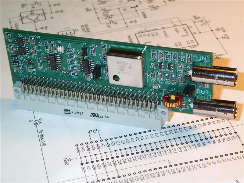
Alpha version cards are being built and tested currently. The first card constructed is pictured above.
This board is much simpler than the main HPSDR cards, so I expect that they would be offered as either bare boards, or as kits as was Atlas. This card uses the larger 1206 surface mount parts for easier manual assembly.
Ideas, comments and suggestions are welcome.
--- Graham, KE9H
DESCRIPTION
It can be configured/populated in several ways.
First, it can be configured to take an external 10MHz signal, such as a sine wave or square wave output from a reference standard or GPS disciplined oscillator, into a BNC input and process it into a square wave and put it on Atlas bus 10 MHz clock line C16.
It can alternately output a square wave to a two pin connector (J2), for direct connection to the AUXCLK-(J8)input on Mercury.
Optionally, it is a way to have an on-bus "instant on" TCXO with more accuracy than the 10 MHz oscillators on either Penelope or Mercury.
The board has a 10 MHz "Input" BNC, and a 10 MHz "Output" BNC connector. The input can be configured to drive the bus, or act as a reference for setting the on-board TCXO.
The "Output" is a way to lock external equipment to which ever 10 MHz source is in use.
There is a multi-colored LED, hooked to the output of a frequency-phase detector comparing the TCXO to whatever is coming in the "Input" connector. It gives both a HIGH/LOW frequency color indication and a visible beat indicator. It is useful for setting the TCXO to within a fraction of a Hz.
The 10 MHz oscillators on the Mercury or Penelope cards have a rated stability of +/- 50 or 100 ppM over wide temperature, or +/- 500 Hz to 1 kHz at 10 MHz. Using the Calibrate function built into PowerSDR, you can set them to WWV or other reference, with an accuracy of about 10 to 30 Hz, but I would still expect them to walk around +/- 50 to 100 Hz over normal room temperature variation.
The (medium performance) TCXO on Excalibur has a rated stability of +/- 1 ppM over wide temperature, or +/- 10 Hz at 10 MHz. I observe that over just normal room temperature variation, it stays within 1 Hz of the calibrated frequency, and will likely age at the rate of 1 Hz every several months.
A (high performance) external 10 MHz GPS disciplined oscillator will typically hold +/- 0.0002 ppM or +/- 0.002 Hz at 10 MHz for as long as the GPS system remains operating.
The card is the same width as Penelope or Mercury, but is only 4 cm. (1.6 inches) high, and takes one slot position on the Atlas bus.
The only expensive part is the TXCO (about USD $45), which is not necessary if you just want to inject a 10 MHz external reference.
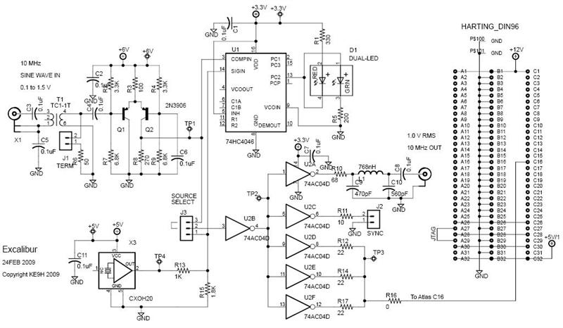
Although the board contains no software, it is compatible with the JTAG chain, so that it will pass through JTAG programming from cards on either side of it.
Schematics:
CURRENT STATUS
March 21, 2009
Alpha version cards are being built and tested currently, by Phil, VK6APH; John, N8UR; Joe, K5SO; and myself, KE9H.
RELATED DOCUMENTS AND LINKS
The PCB cards and schematics are designed in EAGLE Layout Editor
==
Good design notes on conversion of sine-waves to squarewaves and vice versa in frequency standards clock distribution are found at Wenzel's web site:


