METIS
METIS is a high speed PC interface board intended for use with the openHPSDR range of circuit boards. Metis is designed to plug into the openHSDR Atlas bus and is a drop in replacement for an Ozy or Magister USB2 interface board. Metis provides either a 100T or Gigabit (1000T) interface to the host PC. The board uses a large Altera FPGA (providing some 40,000 logic elements) which provides plenty of room for future code updates and new facilities. The user input and outputs (e.g. PTT, CW key, relay driver) that are currently available on the Ozy and Magister boards are provided. However, control of the SDR1000 is no longer supported. All the Ethernet protocol processing is undertaken by the FPGA. Protocols supported include: UDP/IP, DHCP, ARP and ping. A unique MAC address is used by each board and either a static or automatically assigned IP address can be used. Future Metis code updates can be done via the Ethernet connection eliminating the need for special programming adapters.
A minimal openHPSDR receiver would consist of a Metis board, Atlas backplane and Mercury ADC board. The addition of a Penelope exciter board will provide a complete DDC/DUC transceiver.
Project Leader: Phil, VK6APH
Contents
- 1 Update: 23 November 2010
- 2 Update: 4 November 2010
- 3 Update: 13 September 2010
- 4 Update: 30 August 2010
- 5 Update: 15 August 2010
- 6 Update: 11 August 2010
- 7 Update: 1 August 2010
- 8 Update: 15 July 2010
- 9 Update: 23 May 2010
- 10 Update: 8 April 2010
- 11 Update: 15 March 2010
- 12 Update: 5 March 2010
- 13 Update: 2 March 2010
- 14 Update: 11 February 2010
- 15 Update: 31 January 2010
- 16 Update: 29 January 2010
- 17 Update: 14 January 2010
- 18 Update: 27 October 2009
- 19 Update: 27 September 2009
- 20 Update: 26 September 2009.
- 21 Useful info:
Update: 23 November 2010
Beta boards check out OK. TAPR have been advised that Metis is ready for production. Beta FPGA code testing continuing with new features and tuning currently taking place.
Update: 4 November 2010
Beta boards have been manufactured and shipped to Beta testers. Beta Metis boards are running using KISS Konsole and ghpsdr (see http://www.g0orx.blogspot.com/). Expresions of interest to purchase production boards from TAPR can be placed here http://www.hamsdr.com/Home.aspx. Note that you need to login then select Projects > TAPR-HPSDR.
Update: 13 September 2010
Have done some simple speed tests between Metis and my PC. At 100T, full duplex, I can send 1kB payload UDP/IP packets simultaneously in both directions at 96Mbps (12MBps). At 1000T this increases to 560Mbps (70MBps). The delays are in the PC code (untuned C# using .NET Sockets) since the Metis board will operate at 960Mbps (120MBps) but my PC and router won't!
Beta PCBs and parts have been ordered and will be automatically assembled in order to check the design is production ready.
Update: 30 August 2010
Discovery code working. Can also now erase and program the EPCS16 flash memory via Ethernet. This will enable the FPGA code to be updated and maintained without the need for an Altera Byte or USB Blaster. Only major code left to add is I2C so that Penelope etc can be controlled via the Atlas bus.
Bill, KD5TFD, has built his Alpha PCB and has it working 100%. Kevin, M0KHZ, has made some slight modifications to the location of components on the PCB to enable a robotic pick-and-place machine to load parts on the board. Beta PCBs will be manufactured shortly.
Update: 15 August 2010
ARP, ping and DHCP all working. Currently implementing OzyII discovery code.
Update: 11 August 2010
OzyII Alpha PCB is fully functional. Some minor changes to the PCB will be made ready for the Beta run. Alpha PCBs currently being build by Bill, KD5TFD, and Kevin, M0KHZ. Presently adding ARP, DHCP and ping functions to the FPGA code. Basic automatic 100T/1000T network speed detection and switching tested and working.
Update: 1 August 2010
Completed building Alpha PCB and started testing. Works fine at 100T, need to check at 1000T next. Photo of top side of board nearby.Update: 15 July 2010
The PCB layout has been completed by Kevin, M0KHZ. Alpha PCBs have been ordered and are due this week, all parts have been ordered and are available. Verilog code has been written to test the PHY at 1000T and it appears to run OK.
Update: 23 May 2010
V1.1 of the OzyII schematic is available for peer review. The document is here Media:OzyII_v1.1.pdf, note that if you click on a component a descriptive box opens showing full details of the particular component. Detailed checking of the schematic by others will greatly reduce the potential for errors in the Alpha PCB. Comments, corrections and suggestions via the openHPSDR reflector please.
Update: 8 April 2010
Since OzyII will not incorporate and FX2 uP we will need a way of updating the FPGA code. Initially we can use a Byte Blaster or USB Blaster but eventually we will need a simple way for the user to install updated code via the Ethernet port. Two things need to be completed in order to enable this. Firstly, the ability to write to the EPCS16 configuration EEPROM via FPGA code and secondly the ability to have two sets of code in this chip. The first set of code (Factory code) will be loaded at power on if a particular jumper is installed. This code will look for the new FPGA code to arrive at the Ethernet connector. Without the jumper installed, at power on, the FPGA will load the alternative code (called the Application code) which will be the latest OzyII code.
Thanks to some work last year by Michael Wyrick, N3UC, I've been able to write some test code that allows me to read and write to any address in the EPCS16 and also select which of two sets of code to load at power on.
Update: 15 March 2010
MDIO interface to the PHY is now working; can set up its transmit and receive registers. I2C Master implemented in the FPGA for setting up Penelope and general I/O.
Update: 5 March 2010
Have implmented the discovery code in the FPGA and it's working fine. Also connected the 25AA02EA8 to the FPGA and the board now reads its MAC address from the EEPROM at start-up.
Update: 2 March 2010
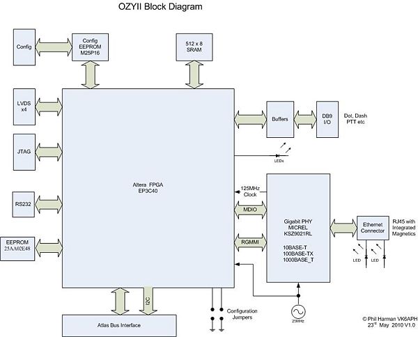
DHCP is now implemented and working so a soft core uP is not immediately requred. The block diagram for the Alpha OyzII PCB has been updated and the PCB layout commenced. It has been decided not to include an FX2 USB interface since the Ethernet PHY provides all the connectivity to the PC necessary. Have completed PC code that sends a broadcast message over the users network looking for an OzyII card. If an OzyII board detects this message it will reply with its IP and MAC addresses. The Verilog code has been simulated in C# and is working against the PC broadcast code.
Update: 11 February 2010
Have now implemented ARP and PING in OyzII so most of the IP Discovery code is now working. My PC will send an ARP request when KISS Konsole first starts to determine the MAC address of OzyII.
Now looking at implementing a soft core uP as an alternative to doing the Discovery code in Verilog.
Update: 31 January 2010
Now have OzyII sending and receiving UDP/IP frames. Have also implemented UDP/IP in KISS Konsole. Still have to add all the IP Discovery code but the concept basically works! Many thanks to Bill, KD5TFD, for dragging me up the Ethernet learning curve :)
Screen shot of KISS Konsole tuned to a Broadcast station below.Update: 29 January 2010
I now have OzyII sending UDP/IP frames to my PC. Using C# .NET Sockets to receiver the data is very straightforward. Next step is to add UDP/IP support to KISS Konsole.
Update: 14 January 2010
I've completed modifying K.I.S.S. Konsole to work with Ethernet data rather than USB by replacing libUSB with SharpPcap. I've also added Ethernet support to Kirk's Ozy code. OzyII now sits on the Atlas bus, works with Mercury and Penny etc and talks to K.I.S.S Konsole.
There is an issue when using the Micrel KSZ9021RL evaluation board in full duplex but I think this is crosstalk due to the long leads from the chip to the edge of the board.
A prototype PCB is presently being layed out.
Update: 27 October 2009
I now have the receive code working in the FPGA and have been able to couple it to Kirk's v 1.7 Ozy code. That enables me to produce audio from the Mercury card using some PC software written by Bill, KD5TFD, that emulates data from PowerSDR or KK over Ethernet. Next step is to add the Ethernet transmit code to Ozy so we can send I&Q data from Mercury to the PC. By replacing the USB interface in PowerSDR or KK we will be able to test the entire system.
Lyle, KK7P, commenced drawing the schematic for OzyII.
Update: 27 September 2009
I now have the CRC32 generator working in the Ozy FPGA. The board can now generate Layer II Ethernet frames without being connected to a PC. This should be the last major building block necessary to complete the board design.
Update: 26 September 2009.
I'm making good progress with the development of a Gigabit interface to the Atlas bus i.e. OzyII (Aussie2).
The choice of a Micrel KSZ9021RL PHY chip looks like paying off. The chip uses the RGMII interface standard which means it only requires 12 pins in order to connect to the associated FPGA. Given the low pin count 'we' (i.e. Lyle KK7P) should be able to support both the PHY and an FX2 chip on the PCB. It's also only needs a single supply, is small, low power and low cost.
We can use the FX2 as a conventional USB interface, just like Ozy/Majster, to program the FPGAs associated Flash memory by making it emulate an Altera
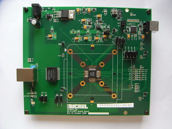
USB Blaster and also perhaps hand off some of the Ethernet protocol processing to it (later on). Micrel provide a very nice evaluation board for the KSZ9021RL (see nearby photo).This has an Eternet connector, access to the RGMII pins and a USB interface. TheUSB interface provides access to read/write all the internal registers of the PHY. There is also a very nice GUI on the PC that they also provide so you can play with all the register settings.
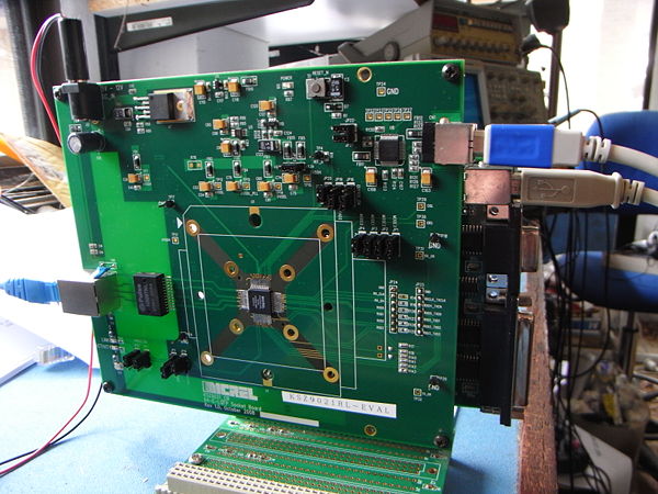
I've been able to interface the evaluation board to an Ozy board (see nearby photo) so that I can write FPGA code to test the PHY in ernest.
By using the USB port on Ozy I can format any Ethernet frame I like on the PC, send it to Ozy and then onwards to the PHY and my lab Ethernet switch. Similarly, any Ethernet frames the PHY receives are by sent to the FPGA and thence via Ozy's USB port back to the PC.
Thanks to Bill, KD5TFD, for this suggestion - it has certainly speeded up development.
We intend to include an FX2 on the final OzyII board to enable it to be used as an Ozy board, enable the FPGA and/or its Flash memeory to be programed via a pseudo Altera USB Blaster and perhaps provide UDP or TCP support.
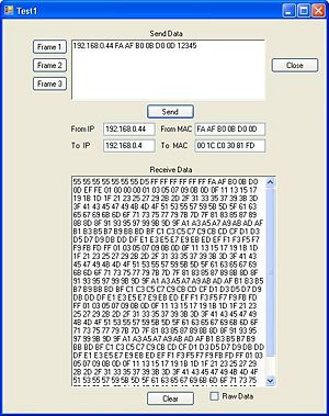
I've written a simple C# program on the PC that allows me to format an Ethernet frame, or send a canned one, to the PHY. The PC sends the entire frame, including calculating the CRC32. I can also display any received Ethernet frames on the PC. Again, there is a screen shot of the PC software nearby.
Being able to generate any type of Ethernet Fame on the PC is so much faster and easier than doing the code in the FPGA. Once I have the basic code working in C# then I can port it to Verilog.
So far this all seems to work just fine. If I use the MAC address of the Ethernet Card in my PC as the 'To MAC address' then my Ethernet Switch correctly forwards the frames to the PC. Similarly the switch learns the MAC address I have use as the 'From MAC address' and returns frames just to the PHY board.
This will be a useful developement platform as we move to more advanced protocols in the future.
The next step is to get the FPGA code to generate the Ethernet preamble plus MAC addresses, get the data Payload from the PC via USB, and calculate and append the CRC32.
I have this code working in simulation but have yet to try it in the actual Ozy + PHY hardware. (Now working in the FPGA - see update above).
Once that is working I can grab Mercury I & Q data off the Atlas bus and send that to the PC via Ethernet. Similary, the demodulated audio and I & Q data can be returned via Ethernet. We will need a modified version of PowerSDR/KK to test this and Bill KD5TFD is already working on ways to do this.
In order to use this initial software it will be necessary to program the MAC address of the PC you intend to use with OzyII into the board. We will provide a Flash memory chip on the PCB that will be programmed with the boards MAC address during manfacture.
With the FPGA <> PHY hardware interface working we can start designing the schematic for OzyII and Lyle KK7P will commence that after his holidays.
By using a large FPGA it offers the potential to add a soft core microprocessor in the future so that the board can run a full TCP/IP stack, UDP etc. e.g. uIP http://www.sics.se/~adam/uip/index.php/Main_Page
Initially we will use the Gigabit PHY as just a fast connection to the PC and use raw frames to communicate.
Feedback and comments are requested via the HPSDR reflector.
Ethernet Notes:
In general, an Ethernet subsystem is divided into two parts: the media access controller (MAC) and the physical device (PHY or line interface). Generally, the MAC handles generating and parsing physical frames and the PHY handles how this data is actually moved to or from the wire. The PHY is just a means of transmitting raw bits rather than logical data packets over a physical link that are connecting network nodes.
Useful info:
- Altera White paper on Ethernet using Cyclone III and NIOS soft core


