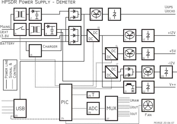
DEMETER
Project Leader: Jeroen, PE1RGE
"Demeter" is the project-name for the HPSDR power supply. Although power supplies are widely available, Demeter will be specifically designed for the HPSDR project.
On the 13th of June 2008, Tiny Demeter is added to the Demeter page. Tiny Demeter has a simpler design. Tiny Demeter will be more suitable for experimenters and allow us to gain some experience before constructing Demeter.
Further information will be presented on this page when it becomes available.
73 Jeroen PE1RGE
Result of the discussion on the HPSDR mailing-list (11th June 2007):
DEMETER SPECIFICATIONS
Input
- 13.8 Volt DC (always 13.8 V or is there a supply range, see remark below)
- 110 Vac (mains)
- 230 Vac (mains)
- Battery (13.8 Volt) input with automatic switchover, Depth of Discharge Quote: "...The recommended end-of-discharge voltage for the SLA is 1.75V/cell..." 1.75*6=10.5V (lowest voltage), Charging the Lead Acid Battery Quote: "...Correctly setting the cell-voltage limit is critical. A typical voltage limit is from 2.30V to 2.45V...", 2.45*6=14.7V (highest voltage).

Input connector
- Powerpole connector for DC 13.8 Volt
- Mains connector: National standard
Output voltages
- Remote switchable voltages
- +5 Volt @ …. Amps
- +12 Volt @ ….. Amps
- -12 Volt @ ….. Amps
Standby supply (for GPS-engine and OCXO)
- Constant on
- +5 Volt
- +15 Volt
- +24 Volt (depends on OCXO used, if possible user definable/adjustable)
Output connector
- ATX-connector
- DIN 41612 (Atlas connectors)
Protection
- Input protection (high/low voltage, polarity)
- Output protection (current limiting, voltage crowbar)
Monitoring
- Input voltage
- Output voltage
- Output currents
- Temperature
Power supply communication
- Atlas backplane
- USB-bus
- 1 wire interface (controlled by a board on Atlas)
- Dumb-interface using the pins T7 and T8 on the Atlas
Connection to the HPSDR
- Using the ATX power connector, communication via the USB bus
- Using the DIN41612 connector using the Atlas backplane for communication
Position of the power supply
- On the Atlas backplane
- In a separate box (outside/inside Pandora)
HPSDR configuration
- Ozymandias - interface module
- Mercury – receiver (5V @ 500mA, 12V @ 200mA, -12V not used)
- Penelope – transmitter (5V @ 300mA, 12V @ 200mA, -12V not used))
- Alexiares - RF Bandpass Filters
- Gibraltar - frequency standard
- Epimetheus - antenna and other switching
- Measured: Ozy + Janus: +12v @ 200mA, +5v @ 180 ma, -12v @ 70 ma
Questions/remarks
- Switching or Linear?
- Internal/External?
- Power dissipation (Convection cooling/ forced air-cooling)?
- Do we need computer monitoring of voltages and currents?
- Include an USB-HUB (use one of the ports for the power supply communication)?
- Configuration (to use or not to use the SDR-1000)? People who use it in combination with the SDR-1000 need less power from the power-supply and are using a custom built supply or the SDR-1000 power supply.
- Will the 13.8Volt really be 13.8Volt or “something” between 11.0 Volt and 15 Volt? In other words: How many people are going to use the HPSDR mobile?
- Linear (A “lot of heat”, not “green”, easy to construct and trouble-shoot)
- Switching (Less heat, more “green”, more noise, more difficult to construct)
- Transformers: From my opinion there will always be a normal mains-transformer, both in the switching and the linear power supply option. Building a switcher for 110Vac/230Vac is too dangerous and complicated (safety regulations) for (less experienced) home-builders. The switcher will be situated in the low-voltage part.
Contents
[hide]Tiny Demeter
Based on the Teamspeak Session from 31st of May 2008 the idea arose to develop a simpler power supply. The working title for this supply became Tiny Demeter.
This supply could be handy for: - experimenters - people who want a simple configuration - temporary solution unitl Demeter becomes available
Tiny Demeter uses the station power supply as main-source. It expects a fairly well regulated 13.6 till 13.8Volts. From this voltage it will generate:
- +12V @ 1Amp
- +5V @ 1.5Amp
- -12V @ -0.3Amp
Current rating can be increased by adding multiple regulating power transistors.
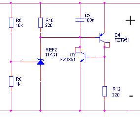
The regulators for Tiny Demeter (and Demeter) will be build from discrete components. The reason for this are the following:
- It allows "current scaling", by adding more power transistors the current handling can be increased
- A discrete regulator gives better temperature stability
- A discrete regulator gives lower output-noise
From the basic idea of having just a few linear regulators the following extras were added:
- Input voltage monitor; This will warn the user when the input power source voltage is too low. (If the input voltage is below a certain threshold the +12V stability cannot be guaranteed, probably causing problems in the HPSDR system.)
- Temperature regulator/monitor; Due to the nature of linear regulators the power dissipation will be around 15 Watts (without extra regulating transistors).
- Crow-bars for each supply voltage; For added safety
- Shunt-resistors to measure the current for each supply-voltage
- Input protection circuit; probably consists of a fuse and a diode OR a fuse and an electronic switch (switch only closes when the input voltage has the right polarity).
The board itself will have a:
- An ATX 20pin power connector attached to its PCB, so it plugs in directly on Atlas
OR
- An ATX 20pin power connector attached to a short cable and mounting brackets which can be used to mount Tiny Demeter on the mounting holes of Atlas
The proposed schematic block-diagram can be found below:
Design Ideas
Here some references are made to components and ideas which I have in mind for the Tiny Demeter design:
Transformers for the switcher:
- http://www.bourns.com/pdfs/pm600_610_620_series.pdf
- http://www.cooperbussmann.com/3/CoiltronicsFinder.html
Linear regulator
- discrete: see schematic
- Linear Technology LT3080
Crow Bar
The principle of the regulator with the discrete components:
The best topology for the switcher has to be determined. At this moment a Push-Pull configuration looks very promising. This will generate the least harmonics as the duty-cycle of the switcher is close to 50%. To get an idea of a push pull switcher one can look here: http://sound.westhost.com/project89.htm
Please note: THIS IS NOT THE DESIGN FOR DEMETER, ONLY AN EXAMPLE OF THE TOPOLOGY.
Suggestion from OZ1HFT
I do not know if this topology makes to much noise. According to the inventor, it can be designed to be low-noised. The primary patents has expired. Please consider the isolated Cuk converter, but not the Integrated Magnetics variant:
- http://en.wikipedia.org/wiki/%C4%86uk_converter
- Other sources in english: http://da.wikipedia.org/wiki/%C4%86uk-konverter#Kilder.2Freferencer
Highlights:
- input and output can be higher and/or lower than the other.
- In CCM both the input and output can be designed to pulsate as little as possible.
- If the diode is paralleled by a switch - and the switch is paralleled by a diode the converter can be bidirectional - good when using an accumulator - also as an UPS.
Components propositions:
- The Cuk capacitor might be a few paralleled ceramic capacitors: (unknown if OK and low-ESR enough) CAP CER 2.2UF 100V X7R 1210: http://search.digikey.com/scripts/DkSearch/dksus.dll?Detail&name=587-1778-1-ND
- Ceramic capacitors are better than electrolytics and do not dry out: Aug 1, 2007, powerelectronics.com: Stacked-Ceramic Caps Brave High Temperatures
- If an over-current detector is needed, it could be a bead current transformer - or this cheap 65uA comparator LMV7239 with 45nS propagation delay. Another solution is to sample the MOSFET-switch on-voltage - as used in this SEPIC-smps: http://dren.dk/carpower.html
- Maybe this smps controller can be used (might not be useful for CCM...): ucc38xx - e.g. UCC3803 (4V UVLO) and UCC3802 (8V UVLO): http://focus.ti.com/docs/prod/folders/print/ucc3803.html , http://search.digikey.com/scripts/DkSearch/dksus.dll?Detail?name=296-11466-5-ND - improved: UC3843, UCC38C43, MIC38HC43, MIC38C43, SG3843, KA3843, ISL8843, TL3843, ISL8843.
- Maybe use this software PWM PIC-controller?:
- GPL - do not know if this is compatible with this sites copyright: A Microchip 16F690 PIC as universal PWM controller for power supply applications Quote: "...Here you find the source code for a Microchip 16F690 PIC assembler program that makes that chip behave like an universal switchmode controller with LCD display...For this reason the current and voltage control is in real time, and not software dependent, other then the initialisation of the chip. No interrupts or routines in the main code are involved in the control of the output voltage or current..."
- main page.
Preliminary design
The following documents contain a part of the design of Tiny Demeter. "Tiny Demeter design.pdf" contains (some) engineering notes. The file "Schematic Prints.pdf" contains the schematic of the switcher, however without the correct values for the components. You can use it to get a general idea of the DC/DC converter design. More details of the design will be added soon!
- Design notes:
- Preliminary (partial) design:
--PE1RGE 08:36, 1st August 2008 (PDT)

