Difference between revisions of "The Tokyo Hy-Power HL-45B Solution"
(→Construction:: improved format) |
(→HL-45B Interface Bill of Material (BOM): adding prices) |
||
| Line 124: | Line 124: | ||
! width="300"|Part Name | ! width="300"|Part Name | ||
! width="100" align="right"|Price ($US) | ! width="100" align="right"|Price ($US) | ||
| + | |- | ||
| + | |Heat SInk: Thermalloy 530614B00000G | ||
| + | |align="right"|xx.xx | ||
| + | |- | ||
| + | |DB-25 Connector and hood (for Penelope interface) | ||
| + | |align="right"|xx.xx | ||
| + | |- | ||
| + | |PC Power Jumper- Fry's | ||
| + | |align="right"|xx.xx | ||
|- | |- | ||
|Q1 - NTE235- Fry's | |Q1 - NTE235- Fry's | ||
| Line 140: | Line 149: | ||
|align="right"|xx.xx | |align="right"|xx.xx | ||
|- | |- | ||
| − | |RLY1 - DPDT - | + | |RLY1 - DPDT - Radio Shack 275-249 |
| − | |align="right"| | + | |align="right"|5.49 |
|- | |- | ||
|BNC Jack Circuit Board mount - Fry's | |BNC Jack Circuit Board mount - Fry's | ||
| Line 149: | Line 158: | ||
|align="right"|14.98 | |align="right"|14.98 | ||
|- | |- | ||
| − | | | + | |3/32" Panel Mount Radio Shack 274-245 |
| − | |align="right"| | + | |align="right"|1.50 |
|- | |- | ||
|R1 - 15 Ohm | |R1 - 15 Ohm | ||
| Line 182: | Line 191: | ||
|align="right"|xx.xx | |align="right"|xx.xx | ||
|- | |- | ||
| − | |Blank Printed Circuit board | + | |Blank Printed Circuit board, 2-sided Copper Clad Cut to 3-3/5 x 5. Can be cut from Radio Shack 265-1499 $3.99 |
| − | |align="right"| | + | |align="right"|3.99 |
|- | |- | ||
|PC rear bracket - (PCI card slot filler furnished with PC cabinet) | |PC rear bracket - (PCI card slot filler furnished with PC cabinet) | ||
| + | |align="right"|0.00 | ||
| + | |- | ||
| + | |Connector to HL-45B: 8-pin MiniDIN (found it at Frys) | ||
| + | |align="right"|xx.xx | ||
| + | |- | ||
| + | |Cable: 1/8" mono or stereo plug to whatever (cut one end of generic patch cable) | ||
|align="right"|xx.xx | |align="right"|xx.xx | ||
|- | |- | ||
Revision as of 10:59, 9 October 2009
The HL-45B is a small compact HF and 6 meter amplifier capable of 45 Watts output on all modes. Band switching is manual, but all required low pass filters are included. Because it requires 5 Watts input to drive it to full power, detailed construction notes are provided to provide a small preamp between the Penelope and HL-45B. Specifications and other information on the Tokyo Hy-Power labs' HL-45B are available at Tokyo Hy-Power's web site. Dick Faust, K9IVB, recommended that we use the FCC data on the HL-45B, if you use the links, you will probably need to rename the files to a name ending with ".pdf" and possibly download the Japanese fonts as requested by the Adobe Reader. The files were readable using Acrobat 9 using the view all files selection on my Mac. Here is the link: FCC files on the Tokyo Hy-Power HL-45B. Dick also mentioned "The schematic shows a 2db pad and the circuit description indicates 3db - might be able to short out and drive directly with Penny". Please let us know if this improves the solution if anyone tries it. Also we are looking for a way to interface PowerSDR with the band changing circuits in the HL-45B. If enough hams are interested, we could put this on our PowerSDR wish list.
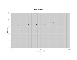
The measured Gain of this amplifier is shown in Figure #1.
Contents
- 1 The Direct Connection Option
- 2 The Full Output Option
- 2.1 Overview:
- 2.2 T/R and Keying:
- 2.3 Schematic Diagram:
- 2.4 NTE 235:
- 2.5 Single-Ended Class A:
- 2.6 Bias Stabilization:
- 2.7 Power Gain:
- 2.8 Harmonics:
- 2.9 Collector Matching:
- 2.10 Base Matching:
- 2.11 Emitter Decoupling:
- 2.12 Component Substitutions:
- 2.13 Wideband Transformers:
- 2.14 Construction:
- 2.15 Layout:
- 3 HL-45B Interface Bill of Material (BOM)
The Direct Connection Option
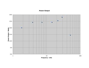
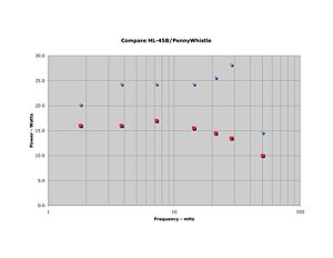
Phil Crosno, N6AS, did the initial work on the selection of this amplifier to provide additional power output for a HPSDR rig. His power output of a directly connected, unmodified HL-45B to a Penelope/Mercury based transceiver is shown in Figure #2. Comparison of the HL-45B to the power output of the PenneyWhistle is shown in Figure #3 (using Penelope as the driver at 13.8 Volts in both cases).
The Full Output Option
Dave Poole AD9DP
October 7, 2009
Overview:
This project set out to develop a 2-watt single ended IPA and keying interface between a Penelope and a Tokyo Hy-Power Model HL-45B Linear Amplifier. Tokyo Hy-Power HL-45B: With a rated output of 45 Watts and band-switchable harmonic filtering, the HL-45B is a good complement to Penelope. The HL-45B is specified for its 45 watts out with 5 watts in, but the experience of AD9DP and N6AS has been somewhat better than that – one can get by through 10m with about a watt, and certainly less than two watts.
T/R and Keying:
The HL-45B has a TTL level TX~/STBY input that can't connected to Penelope simultaneously with a T/R relay. It is further desirable to disable power to the IPA during receive so as not to amplify the output noise of Penelope's output buffers and present it at the T/R relay where might degrade the receiver. In this interface, Penelope controls the 12V coil of generic DPDT relay RLY1 via a connection to Pin 13 on its DB-25 port. One pole of RLY1 enables +12VDC to the IPA, the other pole provides T/R switching. The presence of +12V on the IPA throws switching transistor Q1 into saturation, keying the HL-45B through a 3mm rear panel jack and cable to its 8-pin Mini-DIN control connection.
Schematic Diagram:
NTE 235:
The NTE235 transistor is an aftermarket replacement for the MRF475. It is not necessarily the same thing, but it is adequate, cheaper and more widely available. The remainder of the IPA consists of a pair of wideband ferrite transformers and a minimal number of purchased parts.
Single-Ended Class A:
The strategy behind this project was to sacrifice efficiency (generally, 25-30% at full output) to gain the simplicity of a single-ended class A design. The NTE235 was biased as far into Class A as a board level TO-220 heat sink (Thermalloy 530614B00000G) would allow while holding a junction temperature below 150°C under CW conditions. A peak junction temperature of 125°C was estimated from thermocouple measurements on the device package while idling at 350mA at 12.2VDC in a 25°C ambient.
Bias Stabilization:
The bias point is stabilized by resistor R5 and the Vbe of the device. R5 is minimized, so the bias point may vary somewhat from device to device and it increases with falling Vbe as temperature rises. On two prototypes with different NTE235s, the quiescent current was around 330mA cold, rising to 350mA in thermal equilibrium. The bias point can be adjusted if necessary by trimming resistor R3. The amplifier will stay in class A to about 1watt; beyond that, DC current, efficiency, and harmonic distortion all rise as the conduction angle shifts towards class AB.
Power Gain:
The plot shows that power gain falls with increasing frequency between 7 and 28 Mhz. It is lower at 3.5 MHz due to transformer limitations and is only 6 to 7dB at 50MHz, which is beyond the specifications of the NTE235. The IPA nonetheless realized 0.5 watt out with the maximum 150mW available from a Penelope (into its 1.7:1 VSWR.) This was sufficient to obtain 30W from a HL-45B in the 6m band.
The plot also shows 2 to 4db of gain compression between 1 and 2 watts power output as the NTE235 runs out of collector swing. Up to 1 watt however, the gain was as flat as the available instruments could measure. The chart is no better than ±1db in the absolute because of instrument limitations, and as always in Amateur Radio, YRMV.
Harmonics:
A single-ended topology cannot reject 2nd and other even-order harmonics as does push-pull, and such harmonics are aggravated by the wide collector swing. The measurements in this brief were made with a Wavetek 3000 signal generator, an HL-45B as a predriver, and a 20W precision attenuator, which together were harmonic free to >-60db. The third and fourth columns in the table below thus represent harmonic distortion internal to the IPA. These results would not be good Amateur practice if the IPA were used “barefoot,” but since the intent was to drive the HL-45B which incorporates its own harmonic filtering, the additional complication of harmonic filtering the IPA proved unnecessary. With the IPA, the HL-45 is capable of 45 to 60 watts output below 6m and 30 watts at 6m, but no measurements were taken above 20 watts for lack of an additional pad to protect the analyzer.
Collector Matching:
Motorola App Note AN779 described a push-pull 20 watt IPA based on two MRF475s. A fortuitous 2:1 turns ratio for its output transformer obtained a 6.5 ohm collector load on each transistor which is in the center of its optimal range. Depending on how the transformer was wound, its leakage inductance partially conjugated the -j2.4 ohm capacitive component of the device at 30Mhz. It thus was not surprising that each device yielded 10 watts of the 20 watts output with a class AB conduction angle. In this “hack,“ efficiency is sacrificed to the limitation to one of the integral turns ratios of 2:1, 3:2, or 3:1 for T2. A 3:2 turns ratio results in roughly a 22 ohm load, which is good enough for 2 watts, but far from optimal for the device.
Base Matching:
The base impedance of MRF475 (and presumably that of NTE235) is around 7 ohms at 30 Mhz, but it exhibits more than a 3:1 ratio across the frequency range of interest. As with the collector load, a limited range of turns and impedance ratios is available without introducing greater “Q” into the match and sacrificing bandwidth. However, there is power gain to burn. A 3:1 turn transformer is close enough, but Penelope's output stage won't tolerate the resulting 2:1 or greater VSWR at some cable lengths. (see the article Never Short a Penelope by AD9DP for an explanation.) The solution was to trade off gain for flatness by means of a -3db pad between Penelope and the IPA. The resulting worst case 1.7:1 VSWR is tolerable to Penelope at all reflection angles. If the interface is located in the same cabinet as the Penelope, this precaution is probably unnecessary and greater power output may be possible at 50 MHz.
Emitter Decoupling:
Two watts can be obtained with an emitter-stabilized biasing arrangement if it is well decoupled. In this arrangement, R5 provides DC feedback from the collector circuit to mediate idle current and provide some RF feedback to stabilize power gain in the lower bands. Capacitor C2 is type-critical with respect to flatness because it decouples a very low impedance point. In this particular layout, a 4700pF chip capacitor resonates the parasitic inductance in the foil to boost power gain above 15Mhz. Equivalently, an 820pF disk capacitor could be used owing to its own series resonance at 15Mhz. The layout is drawn with a chip capacitor in hopes the stage can be reproduced without sweep testing or trial and error. Disk capacitors vary in their construction, and use of a disk is likely to require some trial and error with different capacitance values to raise the power gain at 30Mhz while holding down the gain at 4Mhz.
Component Substitutions:
The IPA was prototyped with ¼ watt thru-hole resistors. Only the pad resistors R1 and R2 have any RF impact where a chip resistor might affect performance. R5 can be a half watt or larger resistor but is preferably not a wirewound so as not to form parallel resonances with C2; R3 must be 1 watt or higher rating. The values of R6 and R7 are nearly arbitrary, as Q3 needs sink only 1.4mA to key the HL-45B. C1 and C3 can be either chip or disk capacitors. The design was prototyped with .05uF 50V disk capacitors which worked well owing to a self resonance at 7 MHz. This is a case where more is not necessarily better as a larger value might have inductive internal structure that would produce an undesired self-resonance. C2 was experimentally optimized to 820 pF, so as to provide a series self resonance with its own internal inductance and layout strays so as to decouple even the 1 ohm resistor R5 and provide a gain boost at 25 to 30 MHz. The “production” version was built with chip capacitors and C2 was experimentally optimized to 4700 pF which should be reproducible with the provided layout.
Wideband Transformers:
The RF transformers are supplied by communication-concepts as part numbers R800-9 (pre-wound at 3:1) for T1 and R800-0 (core only) for T2. It is necessary to hand wind both primary and secondary of T2 in a 3:2 ratio. The wire type is noncritical but larger diameter is preferable. With a little patience on the last turn, it is possible to thread 5 turns of 20 gauge hookup wire with .050” diameter insulation. Isolated pads are provided on the layout for solder-mounting T2, leaving open and unused the turn formed by the tubes, which is used in T1.
Construction:
The interface was built on bare PCB laminate and mounted to a rear bracket so as to be mountable in the rear cabinet frame of a desktop PC. Lands were formed by cutting boundaries with a Dremel tool and small cutter and checked for shorts, then components were surface soldered. A matching land must be cut on the rear side foil around the heat sink so the MRF465 and sink could be mounted without the inconvenience of a thermal washer. This technique attains very small parasitics even without the few thru-holes joining the ground plane on both sides. The intent of the lands is not microstrip since no dimension is a significant fraction of a wavelength in G-10 board material even at 50 MHz. The first unit was built in stages hence the jumpers between the IPA and the T/R relay that don't appear in the layout.
Layout:
The following layout can be printed to scale from the accompanying .PDF file and used to check fit ups to whatever components you have. Dimensional targets should be checked; note that they may not display to scale or in the proper aspect on your screen. The layout can be lightly pasted onto a PCB blank, scored through with an Xacto knife, the printout removed, and the lands cut along the score lines. A matching land must be cut on the rear side foil around the heat sink so the MRF465 and sink could be mounted without the inconvenience of a thermal washer.
HL-45B Interface Bill of Material (BOM)
Prices are from internet sources as indicated.
| Part Name | Price ($US) |
|---|---|
| Heat SInk: Thermalloy 530614B00000G | xx.xx |
| DB-25 Connector and hood (for Penelope interface) | xx.xx |
| PC Power Jumper- Fry's | xx.xx |
| Q1 - NTE235- Fry's | xx.xx |
| Q2 - 2N4401 - Fry's | xx.xx |
| T1 - R800-9 Communications Concepts- | xx.xx |
| T2 - R800-0 Communications Concepts- | xx.xx |
| D1 - 1N4401-Fry's | xx.xx |
| RLY1 - DPDT - Radio Shack 275-249 | 5.49 |
| BNC Jack Circuit Board mount - Fry's | xx.xx |
| Pomona BNC 2249-C-XX cables (1 at 14.98 each) | 14.98 |
| 3/32" Panel Mount Radio Shack 274-245 | 1.50 |
| R1 - 15 Ohm | xx.xx |
| R2 - 100 Ohm | xx.xx |
| R3 - 180 Ohm - 1 watt | xx.xx |
| R4 - 15 Ohm | xx.xx |
| R5 - 1 Ohm | xx.xx |
| R6 - 22K Ohm | xx.xx |
| R7 - 22K Ohm - | xx.xx |
| C1 - 0.05UF | xx.xx |
| C2 - 0.0047UF Chip | xx.xx |
| C3 - .05UF | xx.xx |
| Blank Printed Circuit board, 2-sided Copper Clad Cut to 3-3/5 x 5. Can be cut from Radio Shack 265-1499 $3.99 | 3.99 |
| PC rear bracket - (PCI card slot filler furnished with PC cabinet) | 0.00 |
| Connector to HL-45B: 8-pin MiniDIN (found it at Frys) | xx.xx |
| Cable: 1/8" mono or stereo plug to whatever (cut one end of generic patch cable) | xx.xx |
| TOTAL | xx.xx |


