THOR
THOR
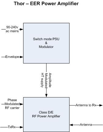
Thor is a high efficiency HF power amplifier using Envelope Elimination and Restoration (ERR) techniques.
EER conventional technique questionable.
EER technique involves splitting the driving signal into phase and amplitude components, in our case we don’t even need to do this as we can produce these components digitally from the baseband I and Q. We use the amplitude to modulate the power supply and the phase signal to drive a class E stage for very high efficiency typically 85-90%. There are some problems to overcome with this design.
There is the problem that the RF signal path through the amplifier and the modulation path through the switching power supply have different delay times, in this case this is not a problem in HPSDR as we can digitally introduce the necessary delays to sync up the two paths.
The main problem which I never overcame is the mosfet capacitances which are typically large and change dramatically when the supply voltage gets low. In low amplitude places of the waveform the capacitances are an order of magnitude greater than normal which detunes the output network and destroys the phase response. Some designs have got round the is problem by only using EER for high amplitudes, for low amplitudes they clamp the supply voltage and bias the amplifier into class AB. This is more complex to achieve and goes against the HPSDR philosophy of high performance or in this case high efficiency.
I believe we need to look at other possible techniques. Specifically we still want to run the PA as close to saturation as possible to maximize the its power efficiency and then tackle the linear problem by using some sort of re-linearization, Cartesian Feedback looks like a good mechanism.
28th November 2011 Steve G1YLB
On Friday's teamspeak session(25th Nov) I hear Phil is working on a new Class E modulation technique which will undoubtedly be very interesting.
On a personal note I have not been able to devote as much time to this project as I would like. I have discovered that raising a young family does not give much spare time ! So if anyone else wishes to take this forward please feel free. Steve G1YLB
The IRS2092 500w Class D Audio Amplifier may be a possible candidate for the envelope modulator
31st July 2010 Steve G1YLB
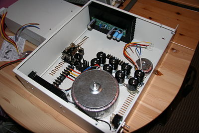
I thought I would start including photos of the power modulator build as it proceeds.
8th May 2009 Steve G1YLB
For the time being I have taken over the project lead from Dan N4XWE in order to get this project off the starting line.
There are still many questions yet to answer over the design of this amplifier e.g multi-band operation via single or multiple PAs. However all the possible designs have one common feature and that is the Pulse Width Modulator (PWM). The PWM consists of two functional modules, the PWM pulse generator and the PWM output amplifier which for now I am calling Thor's Hammer since it is this which supplies the power to the final RF PA. The PWM generator will be implemented in the Penelope FPGA, the ouput of which will be fed to the the "Hammer". Phil VK6APH was kind enough to supply the theory for this which is as follows.
Normally we provide I and Q signals in digital form to Penelope. These are the digital representations of the two signals that for an analogue system we would feed to two balanced modulators. Since we are creating the RF waveform digitally we send the data in serial format at 48ksps. For ClassE we need the envelope of the RF signal and arctan(Q/I). We get the envelope from SQRT(I^2 + Q^2). So rather than sending I @ Q we now send envelope and phase (again, in serial format at 48ksps).
In Penelope we could pass the envelope through a DAC which gives an audio like signal at about 1v peak. This could be fed to the audio input of a conventional PWM modulator - but there is a simpler way.
We can create the PWM switching signals in the FPGA and use the envelope signal to modulate them. This way we stay phase linear and dont need the DAC etc.
We use the phase signal to FM the CORDIC local oscillator. This is very simple, we simply add it to the value in the phase accumalator. Again, all done digitally and totally linear.
One problem we find on the higher frequencies is that the phase relationship between the envelope and the phase get out of wack. Since we have a 122.88MHz clock feeding the FPGA we an use this to delay one of the signals by 1/122.88MHz steps - this should be fine enough adjustment!
This is where I plan to start. At the moment I am building a test circuit similar to what Phil describes below except using a more modern Mosfet and digital drive. This will allow us to test the new FPGA PWM generator code.
At the moment for the PWM amplifier (Hammer) we are considering powering it directly from Mains AC ie a transformerless design.
RF Generator application notes and data sheets
1KW 13.56MHz Class E RF Generator - http://www.ixysrf.com/pdf/switch_mode/appnotes/4apprf_1150.pdf
3KW and SKW Half-Bridge - http://www.ixysrf.com/pdf/switch_mode/appnotes/3ap_3_5kw13_56mhz_gen.pdf
Gate Driver evaluation board - http://www.ixysrf.com/pdf/switch_mode/appnotes/evic420.pdf
DEIC420 and IXDD415 Spice model - http://www.ixysrf.com/pdf/switch_mode/appnotes/9ap_deic420_spice_model.pdf
Interesting RF Power Mosfet - http://www.ixysrf.com/pdf/switch_mode/de275_102n06a.pdf
Interesting digital Driver - http://www.ixysrf.com/pdf/driver_ics/deic420.pdf
30th March 2009 - Time to kick this project back to life I think - Phil VK6APH
PC program for designing Class E amplifiers - http://tonnesoftware.com/classe.html
More information on the transformer-less PWM - http://classe.monkeypuppet.com/viewtopic.php?f=1&t=776
PWM filter simulation software - http://classe.monkeypuppet.com/viewtopic.php?f=1&t=772
Good discussion on practical PWM filters - http://classe.monkeypuppet.com/viewtopic.php?f=1&t=764
1kW output 13.56MHz Class E amplifier - http://classe.monkeypuppet.com/viewtopic.php?f=1&t=764
10m 100w amp discussion, suitable FETs & input matching - http://classe.monkeypuppet.com/viewtopic.php?f=1&t=619
Corrected QST article by Sokal here - http://www.classeradio.com/sokal2corrected.pdf
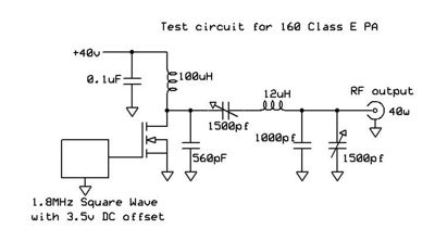
Simple 160m Class E PA
In order to get my feet wet with Class E I built a simple 160m PA from junk box parts. The schematic is shown. It gives 40w carrier out from a 40v supply and efficiency is in the region of 95%. The output tuning seems non-critical and has to be one of the tamest PAs I've ever built. I tried to deliberately blow it up by running it into an open and short circuit - no problems. The drain waveform was absolutely textbook.
The FET is an IRF620 (200v, 6A) I found in my junk box. Perhaps beginners luck but a good start!
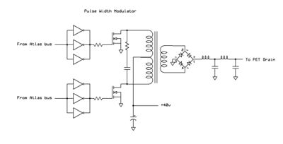
Simple Pulse Width Modulator
It looks like we can make a simple PWM by connecting a couple of FETS to the Atlas bus vis:
Rather than PowerSDR sending I & Q data to Penelope we can instead send the envelope of the signal e.g. Sqrt(I^2 + Q^2) and the phase modulation e.g. arctan (Q/I). The envelope will be used to create the required PWM driver signals for the FET gates, using either the Ozy or Penelope FPGA, and the phase modulation used in the Penelope CORDIC to generate the RF drive signal for the PA.
Other Amplifiers to review
The following looks like a very interesting article and could be a suitable starting point for Thor. It describes the design of a 400w (PEP out) Class E amplifier that covers 80-15m and uses a single transistor. The article is by Josef Hisch, DJ7AW, and appeared in CQ-DL April 2001. Much of the low level RF processing could now be done in Penelope.
The article in German is here Media:400W PA.pdf
An English translation by Horst Grushow, DL6KBF, is here Media:400W PA-English.pdf
Further information on EER techniques can be found in the following publications:
- Reference for all Class D, Class E and EER: RF and Microwave Power Amplifier Design, Andrei Grebnnikov, McGras Hill, 2005 ISBN 0-07-144493-9
- RF Power Amplifiers for Wireless Communications, Steve Cripps, Artech House, 1999, ISBN 0-89006-989-1
- Feedback Linearization of RF Power Amplifiers, Dawson & Lee, Kluwer Academic Publishers, 2004 ISBN 1-4020-8061-1
- Single Sideband Systems & Circuits, Sabin & Schoenike, McGraw Hill, 1995, ISBN 0-07-912038-5
- Power Supplies: Solid State Power Conversions Handbook, Tarter, Wiley Interscience, 1993, ISBN 0-471-57243-8
A very good explanation of High Efficiency Power Amplifiers can be found here - http://www.ericsson.com/ericsson/corpinfo/publications/review/2006_03/01.shtml and here - http://www.highfrequencyelectronics.com/Archives/Nov03/HFE1103_RaabPart4.pdf
The required phase modulated RF signal and envelope(s) will be provided by the Penelope exciter.
Current design work is focused on the switching power supply and modulator.
Why Thor? Thor is the Viking god of Thunder - he was depicted as a huge man with red hair, red beard and red eyes. He was god of the sky, the ruler of storms and the deliverer of thunderbolts and rain. The Vikings believed he rode the heavens in a chariot drawn by two goats. As Thor passed overhead, thunder rumbled from the wheels of the chariot and lightning flashed from sparks created by the hooves of the goats. (He obviously designed mains connected switched mode power supplies!).


