Difference between revisions of "The Antec P183 Solution"
(Added finished Big Iron Photos) |
(Replaced photo with block diagram of P138 Solution System) |
||
| Line 6: | Line 6: | ||
By Ron Cox, [[User:W9KFB|W9KFB]] (with help from the HPSDR group who made all this possible) | By Ron Cox, [[User:W9KFB|W9KFB]] (with help from the HPSDR group who made all this possible) | ||
| − | [[Image: | + | [[Image:P138Solution.pdf|thumb|300px| Block Diagram of the P138 Solution]] |
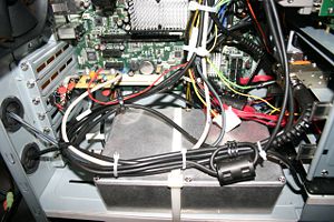
[[Image:P138ready.jpg|thumb|300px| Rear view of Antec P138 case prepared for installation of HPSDR components]] | [[Image:P138ready.jpg|thumb|300px| Rear view of Antec P138 case prepared for installation of HPSDR components]] | ||
Revision as of 23:41, 17 September 2009
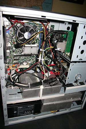
An example of The Antec P183 Solution using the Mercury, Penelope, and Ozy boards and other available hardware and software.
The goal is to build and operate the highest performance amateur radio transceiver that can be assembled using components documented on this wiki. Specifically in one case/enclosure, the following is expected: A totally integrated transceiver with an integrated standard ATX motherboard computer, HPSDR components, and 180 to 500 watts of power output. Not included would be the keyboard, mouse, flat panel screen, audio amplifier low pass or band filters, and antenna tuner. The transceiver must be mechanically and electrically secure so that one would not hesitate to take one to a field day exercise or a DXpedition as a primary rig.
By Ron Cox, W9KFB (with help from the HPSDR group who made all this possible)

