Difference between revisions of "The Antec P183 Solution"
(added open issues) |
(→Open Issues not resolved: FM deviation issue is resolved) |
||
| Line 130: | Line 130: | ||
=== Open Issues not resolved === | === Open Issues not resolved === | ||
| − | |||
#Mike meter reporting 10LogV instead of 20LogV in TX mode. | #Mike meter reporting 10LogV instead of 20LogV in TX mode. | ||
Revision as of 15:12, 16 October 2009
An example of The Antec P183 Solution using the Mercury, Penelope, and Ozy boards and other available hardware and software.
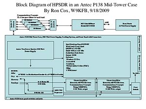
The goal is to build and operate the highest performance amateur radio transceiver that can be assembled using components documented on this wiki. Specifically in one case/enclosure, the following is expected: A totally integrated transceiver with an integrated standard ATX motherboard computer, HPSDR components, and 180 to 500 watts of power output. Not included would be the keyboard, mouse, flat panel screen, audio amplifier low pass or band filters, and antenna tuner. The transceiver must be mechanically and electrically secure so that one would not hesitate to take one to a field day exercise or a DXpedition as a primary rig.
By Ron Cox, W9KFB (with help from the HPSDR group who made all this possible)
Contents
Enclosure
Antec's P183 case brings you top performance and unique style, with its three-layer, sound-deadening panels. Inside, a separate lower chamber houses your power supply (purchased separately), isolating its heat and reducing system noise. The upper chamber comes standard with rear and top 120 mm TriCool fans, with spaces for an optional front 120 mm fan, and a middle 120 mm fan. These two optional fans were mounted to cool the RF power amplifier components.
The three-layer side panel and front door stifle system noise for a quiet experience. Front-mounted ports give you easy access to two USB 2.0 connectors, one IEEE 1394 connector, and audio jacks. Rear panel features external controls for the fans in the upper chamber.
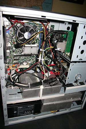
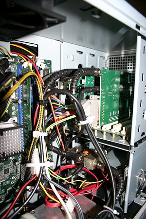
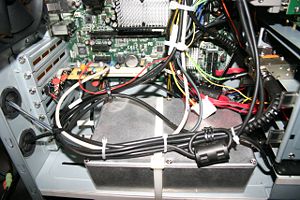
You'll have all the room you need to build your HPSDR system in this case, with bays for four external 5.25" drives (used for the HPSDR components), one external 3.5" drive and six internal 3.5" drives. There's space for an ATX motherboard up to 12"(W) x 9.6"(L), seven expansion slots, and rubber-grommeted holes on the rear for coax cable entry and exit. A built-in cable organizer behind the motherboard tray keeps the cables under control.
Power Supply
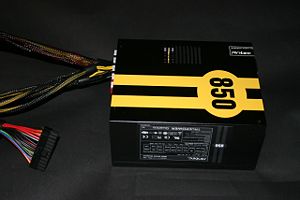
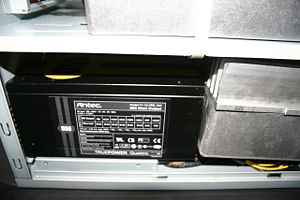
The TruePower Quattro 850 Watt Power Supply Unit includes four +12V outputs at 25 Amperes each, that deliver safe and reliable power to the transceiver componets. The protective circuitry is industrial-grade and includes OCP (Over Current Protection), OVP (Over Voltage Protection), SCP (Short Circuit Protection) and UVP (Under Voltage Protection).
TruePower Quattro power supplies generate less heat than a typical ATX power supply because they are designed for high efficiency. This keeps the power supply cooler and prolongs its working life. The unit has achieved 80 PLUS® Certification[1], the latest independent standard in power supply efficiency. The supply has an Universal Input, allowing it to connect to any AC source between 100 ~ 240V with no selection switch. It also features an advanced cable management system which allows you to only use the cables you need to reduce clutter and improve air flow. Five 6-pin output sockets are provided to power different HPSDR components.
Motherboard, CPU and OS
Any motherboard will fit in this large enclosure, but an Intel DG35EC was just removed from another project with an Intel Core2 Quad and 4 GB of DDR2 memory. As cost was not an object in this project and performance was the object, the motherboard and CPU selection was made.
From System Properties: System: Microsoft Windows XP Professional, Version 2002, Service Pack 3 Computer: Intel® Core™2 Quad CPU, Q8200 @ 2.33GHz, 2.32GHz, 3.24GB of RAM, Physical Address Extension.
HPSDR Components
| Part Name | Price ($US) |
|---|---|
| Atlas Kit- TAPR | 35.00 |
| Mercury RX - TAPR | 329.00 |
| Penelope TX - NT-Electronics | 357.54 |
| Ozymandias-mini - NT-Electronics | 214.79 (Preliminary) |
| TOTAL | 936.33 |
Complete Bill of Material (BOM)
Prices are from NewEgg Web site unless indicated by *.
| Part Name | Price ($US) |
|---|---|
| Antec P138 Case | 134.99 |
| Intel DG35EC Motherboard | 87.99 |
| Intel Core 2 Quad Q8200 2.33GHz 4MB L2 Cache LGA 775 95W Quad-Core Processor | 149.99 |
| Rosewill RCX-Z2 7 blades 80mm reverse ball bearing fan CPU Cooler | 19.99 |
| G.SKILL 4GB (2 x 2GB) 240-Pin DDR2 SDRAM DDR2 800 (PC2 6400) | 64.99 |
| 64GB SSD Kingston | 149.99 |
| Microsoft Windows XP Professional SP3 32-bit for System Builders - OEM | 134.99 |
| Pomona BNC 2249-C-6 cables (5 at 14.98 each)* | 74.90 |
| HPSDR Components* | 936.33 |
| TOHTSU Coaxial Relay CX 230* | 95.00 |
| Misc. Small parts (nuts, bolts, standoffs, carbide drill bit for drilling steel, audio and PTT jacks & cables, BNC antenna connector* | 30.00 |
| Communications Concepts AN762 140 Watt HF Amplifier in a Hammond 7.3X4.7X2.0 Dicast Aluminum Alloy Box with connectors* | 144.00 |
| Communications Concepts AN762 180 Watt HF Amplifier in a Hammond 7.3X4.7X2.0 Dicast Aluminum Alloy Box with connectors and Model 55 Heatsink* | 205.00 |
| TOTAL | 2228.16 |
Lessons Learned
1. Its all about grounding. Avoid ground loops on sensitive and long mike inputs to Penelope. Use a large gauge ground wire from each of the amplifier's to to the back of the rig and terminate each under one of the computer power supply's mounting screws.
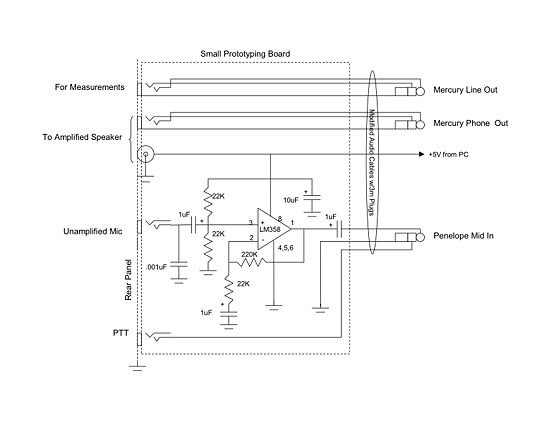
2. We tried to use the analog mike input on the Penelope, but found that the electrical noise level was to high. We then reduced the software gain by 20 dB by changing the "into_ozy11.bat" file to disable the 20 dB mike boost. Next we built an external 20 dB mike amp to get the mike level correct. Details on building this interface circuit follows in the next section.
Analog Mike Preamp Circuit Diagram
Open Issues not resolved
- Mike meter reporting 10LogV instead of 20LogV in TX mode.
