The Tokyo Hy-Power HL-45B Solution
The HL-45B is a small compact HF and 6 meter amplifier capable of 45 Watts output on all modes. Band switching is manual, but all required low pass filters are included. Because it requires 5 Watts input to drive it to full power, detailed construction notes are provided to provide a small preamp between the Penelope and HL-45B. Specifications and other information on the Tokyo Hy-Power labs' HL-45B are available at Tokyo Hy-Power's web site. Dick Faust, K9IVB, recommended that we use the FCC data on the HL-45B, if you use the links, you will probably need to rename the files to a name ending with ".pdf" and possibly download the Japanese fonts as requested by the Adobe Reader. The files were readable using Acrobat 9 using the view all files selection on my Mac. Here is the link: FCC files on the Tokyo Hy-Power HL-45B. Dick also mentioned "The schematic shows a 2db pad and the circuit description indicates 3db - might be able to short out and drive directly with Penny". Please let us know if this improves the solution if anyone tries it. Also we are looking for a way to interface PowerSDR with the band changing circuits in the HL-45B. If enough hams are interested, we could put this on our PowerSDR wish list.
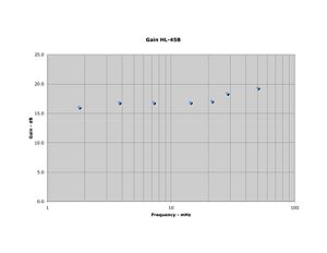
The measured Gain of this amplifier is shown in Figure #1.
Contents
The Direct Connection Option
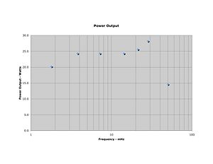
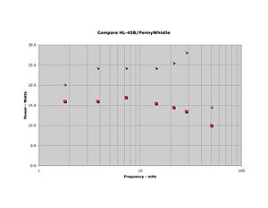
Phil Crosno, N6AS, did the initial work on the selection of this amplifier to provide additional power output for a HPSDR rig. His power output of a directly connected HL-45B to a Penelope/Mercury based transceiver is shown in Figure #2. Comparison of the HL-45B to the power output of the PenneyWhistle is shown in Figure #3 (using Penelope as the driver at 13.8 Volts in both cases).
The Full Output Option
Dave Poole AD9DP
October 7, 2009
Overview:
This project set out to develop a 2-watt single ended IPA and keying interface between a Penelope and a Tokyo High Power Model HL-45B Linear Amplifier. Tokyo High Power HL-45B: With a rated output of 45 Watts and band-switchable harmonic filtering, the HL-45B is a good complement to Penelope. The HL-45B is specified for its 45 watts out with 5 watts in, but the experience of AD9DP and N6AS has been somewhat better than that – one can get by through 10m with about a watt, and certainly less than two watts.
T/R and Keying:
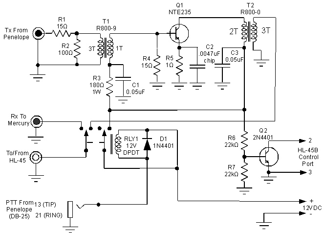
The HL-45B has a TTL level TX~/STBY input that can't connected to Penelope simultaneously with a T/R relay. It is further desirable to disable power to the IPA during receive so as not to amplify the output noise of Penelope's output buffers and present it at the T/R relay where might degrade the receiver. In this interface, Penelope controls the 12V coil of generic DPDT relay RLY1 via a connection to Pin 13 on its DB-25 port. One pole of RLY1 enables +12VDC to the IPA, the other pole provides T/R switching. The presence of +12V on the IPA throws switching transistor Q1 into saturation, keying the HL-45B through a 3mm rear panel jack and cable to its 8-pin Mini-DIN control connection.
Schematic Diagram:
====NTE 235:==== The NTE235 transistor is an aftermarket replacement for the MRF475. It is not necessarily the same thing, but it is adequate, cheaper and more widely available. The remainder of the IPA consists of a pair of wideband ferrite transformers and a minimal number of purchased parts. ====Single-Ended Class A:==== The strategy behind this project was to sacrifice efficiency (generally, 25-30% at full output) to gain the simplicity of a single-ended class A design. The NTE235 was biased as far into Class A as a board level TO-220 heat sink (Thermalloy 530614B00000G) would allow while holding a junction temperature below 150°C under CW conditions. A peak junction temperature of 125°C was estimated from thermocouple measurements on the device package while idling at 350mA at 12.2VDC in a 25°C ambient. Bias Stabilization: The bias point is stabilized by resistor R5 and the Vbe of the device. R5 is minimized, so the bias point may vary somewhat from device to device and it increases with falling Vbe as temperature rises. On two prototypes with different NTE235s, the quiescent current was around 330mA cold, rising to 350mA in thermal equilibrium. The bias point can be adjusted if necessary by trimming resistor R3. The amplifier will stay in class A to about 1watt; beyond that, DC current, efficiency, and harmonic distortion all rise as the conduction angle shifts towards class AB.


