HELIOS
Contents
[hide]Helios Small Transmitting Loop Antenna and Controller
This project describes a small transmitting loop antenna and controller/motor/tuning capacitor combination that connects to the Atlas backplane and automagically keeps a loop antenna in tune as you change the frequency of any HPSDR.
Please note that this project is a “WORK IN PROGRESS” and not intended to be taken as a fully-operational, well-documented fully-tested product. Currently, the prototype is operational, and I am confident that anyone who wishes to duplicate a similar project can be successful, but as yet, all the T’s are not crossed nor are the I’s dotted. Hopefully that will all happen in a timely manner, but until then, please don’t expect all the information here, and especially the code, to be either complete or of rigorously professional quality. If you can’t find the information here that you want, please email me and I’ll do everything I can to provide it. Also please note that as a work in progress, I welcome, and even solicit, your ideas, suggestions, and comments (and maybe even some criticism!). Any errors or mistakes herein are mine and mine alone. (Mea culpa, in advance.) Please let me know about them and I’ll correct them ASAP. Contact me at kenklein@austin.rr.com or Tommy, KV5T at thollingsworth1@austin.rr.com.
We are currently working on a board layout that can be gerbered. This will allow us to buy a quantity of boards much cheaper than the prototypes. We will announce to the group when we are ready to buy in quantity. In the meantime, drop us a line if you want to get on our list of the interested.
Parts may be populated for an on-board power supply if you want to mount the board away from Atlas.
The Name
Helios was the Sun god, of course, and the name means radiant or shining. We certainly hope that this antenna radiates! Also, it is the root for helical, which means “in the shape of a coil”; which fits fairly well too. So Helios it is.
The Project
In these days of antenna restrictions, there has been much discussion of small, easily transported, and discretely deployed hf antennas. One of these antennas is the small transmitting loop, which most generally consists of copper tubing formed in a loop with diameters ranging from less than a foot (for vhf use) to large structures intended for 80 and 160 meters. The loop circumference can be less than 1/10 wavelength and the loop is brought to resonance with a capacitor across the endpoint of the loop. Efficiencies can run very high, even into the 90 percent range, and the antenna seems to operate quite well even close to the ground. The loop, however, exhibits extremely high Q, and bandwidths can be in the low tens of kilohertz. This necessitates constantly retuning the antenna capacitor to resonate the desired operating frequency.
The controller described here reads frequency information from the Atlas backplane in I2S format and converts the frequency data into an index into a lookup table in a PIC processor. The lookup table then provides a pre-programmed capacitor position to a motor driver that positions the capacitor at the proper location to resonate the antenna.
The Antenna
There is a plethora of information on small transmitting loops in the ARRL Antenna Book as well as numerous sites on the web. A couple of the most comprehensive are W2BRI’s site ([1]) and AA5TBs site ([2]). The DX Zone has a list of exhaustive links as well: ([3]). Be sure to note the design spreadsheet on AA5TBs site, which is an invaluable design tool. At least one loop is available commercially from MFJ, although it is pricey and it doesn’t control from receiver frequency, but is tuned for minimum SWR.
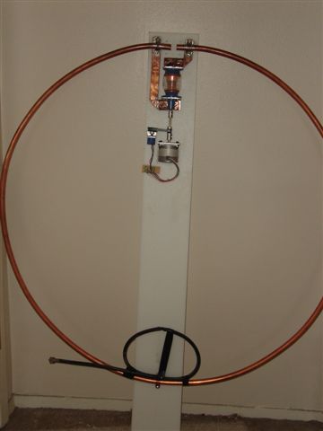
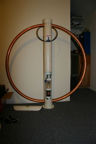
A typical design which has been built as a prototype is described by Robert Capon in “You Can Build: A Compact Loop Antenna for 30 through 12 Meters”. This article is available from the QST archives on the ARRL website. It’s a very simply constructed 3-foot diameter loop using 5/8-inch copper plumbing tubing and resonated with a capacitor. The prototype for this project has been built using this article as a guide. It should be noted, however, that any loop antenna, so matter what size or configuration, can be tuned using this controller. In fact, any antenna tuner that can be tuned from a rotating shaft or any antenna that can be tuned using a variable capacitor or variable inductor can be used as well.
The Controller
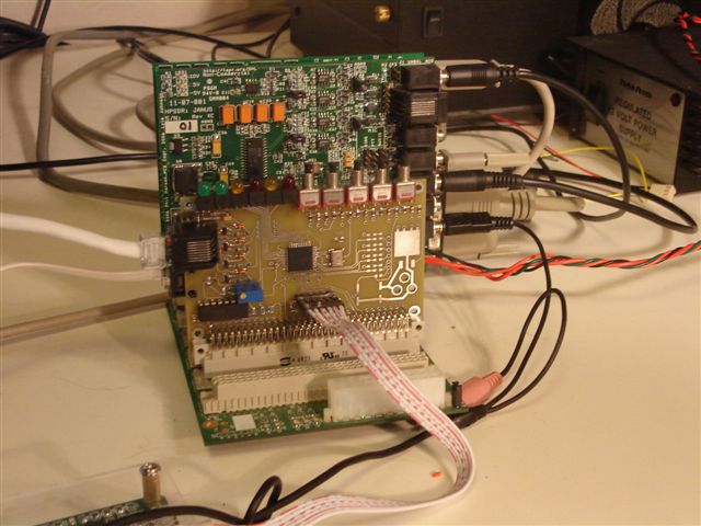
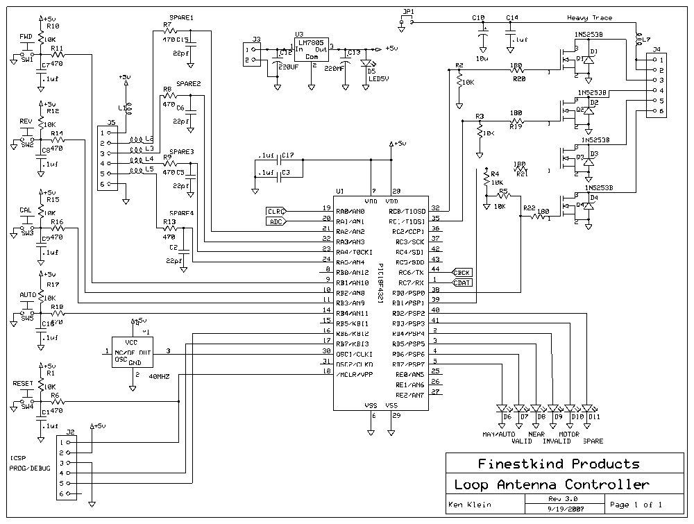
The controller is designed on a 2.5 by 3.75-inch PWB and can either be plugged directly into the Atlas backplane, or alternately mounted away from the backplane and connected to the Atlas by three signal wires and a ground. The controller can be powered from the Atlas backplane or alternatively, powered from an on-board 5-volt regulator. The power can then be supplied by a wall wart delivering anywhere between 8 and 20 volts dc. There are five switches and six indicator lights that operate the controller. These switches can be mounted on the PWB or can be located off-board. Dual footprints are provided for either miniature screw terminals or headers. Motor voltage, being significantly higher than used by the board electronics, is connected separately. The board has two RJ-45 type jacks; one for an eight-wire CAT5 or CAT6 cable that is used to power the stepper motor; the second is for a four-wire telephone cord that brings the position pot signals to the board. A six-pin header connects to an in-circuit programmer to initially program the PIC. There are a number of spare inputs for experimentation and expansion. The controller takes digital signals corresponding to the SDR DDS frequency and positions the antenna tuning capacitor so that it resonates the antenna at, or very near, to this frequency. As the frequency of the SDR is changed over the range of the antenna, the antenna tuning motor/controller will keep the antenna at resonance. Since the antenna exhibits the same high Q performance while receiving as during transmitting, the antenna needs to be tuned for reception as well. Note that this controller will also be able to be adapted to many types of motor-driven local or remote antenna tuners to offer the same “always tuned” performance.
The heart of the controller is a PIC 18F4321 processor, which are normally available from Mouser and other suppliers for about $5.00 ea. Microchip has an extensive website and tons of free software as well as a free IDE. The 18F4321 is used since it has internal communication ports, A/D converters, and PWM motor controllers. If using the PWB developed for this project, you will need a programmer capable of programming the 18F4321 through the in-circuit port, and use the free IDE from Microchip. These programmers are available on Ebay starting at around $30.
On the Atlas backplane, there is a bit stream in I2S format that contains, among other things, 32-bit binary-format frequency information. This frequency information is decoded to derive an index into a lookup table implemented in the PIC. The output of the lookup table is the number of steps (from an index) that the motor must turn to arrive at the resonant point of the antenna corresponding to the input frequency.
A routine is provided to calibrate the controller for each tuning point of the antenna. To calibrate a particular frequency, the transmitter is set to “TUNE” at a particular frequency and a forward or reverse button on the controller is pressed to tune the antenna for lowest SWR. Once reached, the calibrate button is pressed to record the position in the lookup table. For positions outside the band, an antenna analyzer can read the swr or the controller can be calibrated from maximum received signal strength.
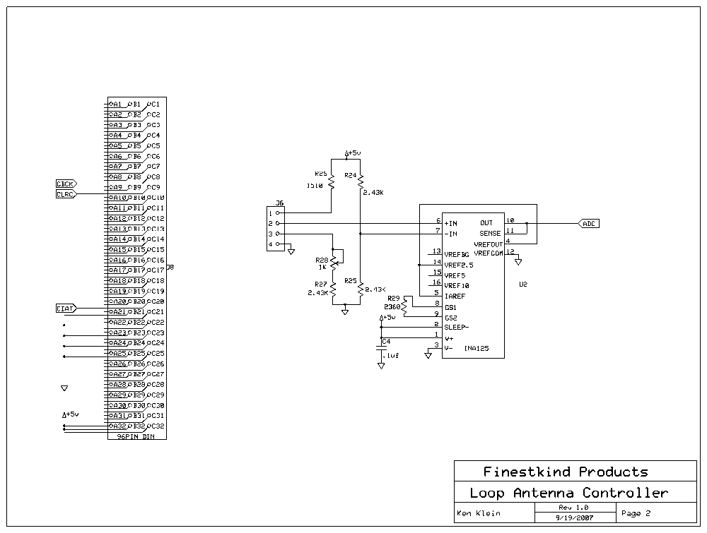
The controller also contains a TI INA125P precision instrumentation amplifier that amplifies the output of a bridge circuit. One leg of the bridge is the potentiometer that follows the position of the capacitor shaft. This position potentiometer is used to accurately locate the index position at minimum usable capacitance. All frequencies are then calibrated as a number of steps of the stepper motor from this index position. When the controller is first powered, or reset, the motor locates and resets to this index position, then, if the receiver is in operation, immediately tunes to the operating frequency.
Note also that there are a number of inputs to the controller that are not used. These are for spare inputs, whether switches or voltage inputs. There is also one unused indicator light.
The Motor
Almost any five- or six wire unipolar stepper motor that can develop sufficient torque to operate the selected capacitor can be used. (Bipolar stepper motors can be used, but would necessitate minor wiring changes on the PWB as well as code changes. Dc motors would require significant code changes as well as wiring changes and won’t be detailed here.) Ebay is a great source for these types of steppers at reasonable prices. Voltage ratings are generally not as important as a stepper can be driven with significantly higher or lower voltage than rated as long as the current is limited.
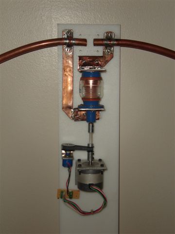
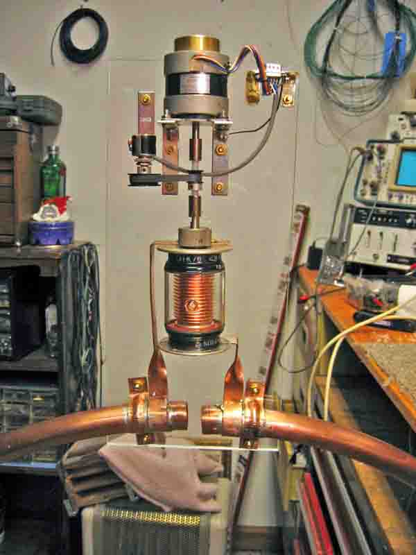
On the prototype, a 1.8 degree/step stepper motor is directly coupled to a ¼ inch insulated shaft (remember that the cap has about 5KV on it at resonance!) that is coupled to a 22-turn vacuum capacitor. On the ¼ inch shaft is a sprocket that drives a short timing belt. This couples the shaft to a 10-turn position potentiometer with an overall turns ratio of 2.2:1. Thus, 22 turns on the capacitor shaft equals 10 turns of the pot. This pot position provides the “index” point at one end of the capacitor travel from which all other positions are derived.
The voltage fed to the stepper motor is adjusted to provide enough torque to operate the capacitor shaft, but not much more. Should a malfunction cause the motor to overdrive the limits of the capacitor, the motor simply stalls without damaging the cap.
The Capacitor
The tuning capacitor must withstand a considerable amount of high voltage, necessitating either a big “bread slicer” transmitting cap or, preferably, a vacuum cap. Voltages of 4 or 5 kV are typical at 100 watts; and past 15kV at 1000 watts. Tuning ranges go from 5pf up to several hundreds of pf. For the compact loop described above, and at 100 watts, a capacitor that tunes from 5pf up to 100 pf. provides a tuning range roughly between 10mHz and 30mHz. If a mechanical “bread slicer” is used, a two section cap is generally preferable since the each of the ends of the loop can be connected to each stator and the rotor rotates between them. This keeps the overall loop resistance low, since the loop connections do not have to be made through the rotor wipers. MAX-GAIN systems, at [4] is a good source for surplus vacuum capacitors. Ebay is also a fertile ground for searching for a suitable cap. There are several Ukrainian sources at bargain prices, but shipping times can run several months, and shipping damage has been reported with these as well.
If you opt for a “bread slicer”, note that the entire range is covered in only ½ turn of the shaft. I have not experimented with these, but I would imagine that you would need a gearbox in front of the cap to provide sufficient resolution. Indexing would be simplified, however, since you could merely stall the motor against the stops to index the shaft.
It might be noted here that the typical vacuum cap has about 22 turns end to end; with a stepper motor that has a 1.8 degree/step increment, this results in 200 steps for one motor shaft rotation. To turn the cap its full range then requires 4400 steps. The PIC, however, only has enough memory for about 2000 steps. In order to encompass the full range of the cap, the motor actually double-steps for each single position increase. In preliminary testing, this resolution seems to be quite adequate for operation while keeping the SWR very low. If one needed higher resolution, it would be fairly easy to recode over a smaller frequency range.
The Database
There are several databases on the HamSDR website in the Public Download directory and “Loop Antenna” folder. [5] Currently, you can find the code, the BOM and the CAD files. The CAD files use proprietary applications that you can download from ExpressPCB [6] website for free. For convenience, I used ExpressPCB for the prototypes, and you can view the schematics as well as the current board layout using these tools. For higher volumes, we need gerber files and we are now in progress of using Eagle schematic and layout applications to generate these files. As they become available, I will update the database with these files. Please note that the board described in the files has just arrived and will be checked out very soon. Hopefully, no changes will have to be made, but at this point it is not certain. Note also that resistor values in the bridge circuit will almost certainly have to be modified.
The Code
The code needs more documentation, of course. (Doesn’t it always?) I am certainly not an expert at PIC programming, and I would imagine that an accomplished coder would laugh at my code, but it works so I offer it freely and will be making improvements in the future as well as making progress in further documentation. The following is a description that I hope might help those who want to modify the code to fit their own application.
At first, the processor is initialized and constant names are defined, and interrupts vectors are stated. The first section of the operational code decodes the I2S bus frequency data. You can find descriptions of the I2S bus on the web; it stands for Inter-Integrated circuit-Sound format.
Here is a description from Phil Harman of the I2S bus data on the Atlas Backplane:
Command and control data is broadcast over the Atlas bus (C20) for use by other cards e.g. Mercury and Penelope. The data is in I2S format with the clock being CBLCK and the start of each frame being indicated using the negative edge of CLRCLK.
The data format is as follows: <[48]PTT><[47:44]address><[43:12]frequency><[11:8]band><[7:1]OC><[0]mode> for a total of 49 bits. Frequency is in Hz and 32 bit binary format and OC is the open collector data on Penelope.
Phil further reports that the signals on the Atlas bus are correct in SVN under ..../Altas/Atlas to Janus V2-OzyV2-Penelope Interface.xls –
Using this information, the code programs the USART to receive the clock and data as well as the start frame signal. Once a frequency is received it is compared with the last value of frequency that has been received. If an identical frequency value is received, then the program continues execution. If the two frequencies are not identical, then the frequency acquisition routine is repeated until two identical frequency acquisitions have been received. This provides some measure of “glitch” protection and keeps the motor from chattering during tuning. Note that once received by the UART, each data byte is in wrong order and has to be flipped end for end. The code grabs the frequency information, selects the appropriate bits, shifts it and subtracts from it to provide a zero index at the lowest frequency in use. The offset in the code is then added to bring the address to the first location in the lookup table, which is currently 0CF0. Increasing frequency moves upward in the table. As it is now, the lower frequency bits are truncated so as to provide frequency in 8Khz blocks; therefore, each entry into the lookup table covers 8 KHz. Note that if greater resolution is desired, it would be an easy modification to the code to provide any desired resolution over a selected bandwidth within the capacity limits of the PIC processor.
The next section of code determines if the entry is valid, near-valid or invalid. The MSB of each entry is initially zero. When an entry is calibrated, the MSB is set to one to indicate that the entry is now valid (i.e. calibrated). If the code does not find a valid entry at the index into the lookup table, it examines the next higher, then the next lower entry and if one of these are valid, it uses the valid entry for tuning. If neither the next higher or lower entry is valid, the code examines the second higher and second lower entry for a valid entry. If successful, it uses this value from the lookup table.
If the initial entry into the table is successful, the VALID flag is set, which ultimately sets the VALID indicator light after tuning. If one of the four subsequent entries into the table is successful, the NEAR-VALID flag is set, which ultimately sets the NEAR-VALID indicator light after tuning. If no valid entry is found, the INVALID flag is set, and the unit does not tune to the frequency.
Of course, if this feature is not desired, the lookup table entries can all be preset with the MSB set to 1. (Note that the current code is programmed this way for testing.)
The next section of code compares the current position of the shaft with the target position found in the lookup table. If greater, the forward flag is set; if less, the reverse flag is set.
The next routine in the code is the step routine, which steps the motor exactly two times in the direction specified by the forward and reverse flags. Motor speed is controlled by a timer that sets the dwell time for each step. Since in the current implementation of the antenna, a 1.8 degree motor is used that provides 200 steps per turn of the shaft. Since the capacitor requires 22 turns over its complete range, we would need 4400 steps to encompass the whole range of the capacitor. Space in the PIC is limited to about 2200 entries, so the motor is stepped twice to provide complete coverage. This results in a resolution of about 8KHz per double step of the shaft. Of course, a smaller range could be programmed allowing increased resolution.
After each double step of the motor, the position value is either incremented or decremented so that the currentposL and currentposH always contain the correct position of the shaft.
After the motor is stepped in the proper direction, program execution is returned to the beginning to re-acquire the current frequency and the process is repeated.
There is an index routine that is executed on power up or upon pressing the RESET pushbutton that causes the motor to reverse until the A/D converter that is monitoring the position potentiometer reaches the pre-programmed index position. Once this index position is reached, the currentposH and currentposL values are cleared, and program execution commences with frequency acquisition.
There is only one interrupt routine which places the unit in the manual (calibrate) mode. This routine continuously samples the forward, reverse, calibrate, and auto switches. If either of the FWD or REV pushbuttons are pressed, the step routine is executed to step the motor once in the direction indicated. The AUTO pushbutton exits the routine and returns execution to the program beginning. The CAL pushbutton executed the calibration routine.
When the CAL routine is executed, a frequency sample is taken which provides the proper index into the lookup table for the frequency that is currently tuned. Current position information is given by currentposH and currentposL. It remains only to put this information into the lookup table.
The PIC chip can be programmed on the fly, but the procedure is somewhat convoluted. The code area that needs to be programmed must first be erased, then reprogrammed with the new data. Erasures can only be performed on 64 byte blocks; Reprogramming is only possible in 8-byte blocks. Therefore, a 64-byte block needs to be saved in RAM then updated with the new data entry. (The new data consists of the position information gleaned from currentposH and currentposL. Note that the MSB is also set to indicate a VALID entry.) The 64-byte block in the lookup table is then erased. Then the saved and updated 64-byte block is reprogrammed into memory in eight 8-bytes blocks. (All this just to update one two-byte entry in the lookup table!)
Operating Instructions
The controller has two basic modes in which it operates; a manual (or calibrate) mode and an operational mode. While in the operational mode, the controller reads frequency information from the Atlas backplane and sets the capacitor position to a pre-programmed position that resonates the antenna. Note that the SR (Spur Reduction) button on the SDR should be set to OFF. This causes the exact tuned frequency to be sent to the antenna controller.
To operate in manual mode, press either the forward or the reverse pushbuttons. When the forward button is pressed the motor will increase capacitance (lower the resonant frequency) until the button is released. When the reverse button is pressed the motor will decrease capacitance (raise the resonant frequency) until the button is released.
To calibrate at a frequency point, set the SDR to the tune position, and activate the swr meter. Then press the FORWARD or REVERSE button until the minimum swr reading is read on the meter. Once this minimum is found, press the CALIBRATE button. The position of the stepper motor (and the capacitor shaft) will then be burned into PIC memory. Once calibrated, returning to a frequency within the band causes the controller to return the motor to this calibrated position.
Note that as currently programmed, the smallest frequency step that the controller makes is 8 KHz. Once a position is calibrated, tuning anywhere within this 8 Khz step will position the motor at the precalibrated position.
One method for calibration would be to use an antenna analyzer that outputs a very low amount of power into the antenna. Tune to a frequency at the bottom of the band that you want to calibrate, and calibrate this point as described above. Then slowly raise the frequency of the analyzer until the swr jumps significantly. This indicates that the controller has moved the cap to an uncalibrated position. Recalibrate at this position, then move to the next uncalibrated position. Continue until all points in the band are calibrated.
After calibration is completed, press the AUTO switch to exit the Manual mode and return to automatically tune the antenna.
On power up, or whenever the RESET button is pressed, the unit seeks to the index position, resets the index point, then, if the receiver is powered, tunes to antenna to the received frequency (if calibrated).
There are five indicator lights currently implemented on the unit; VALID, NEAR VALID, INVALID, MOTOR IN MOTION, and AUTO MODE.
The AUTO MODE light is lit whenever the unit is powered and not in manual mode.
The MOTOR IN MOTION light is lit whenever the motor is moving either to the index point or to a pre-calibrated position
Depending upon how the unit is programmed, the VALID, INVALID, and NEAR VALID lights operate as follows:
In each lookup table entry, the MSB indicates whether or not the entry has been calibrated. If the MSB is set, the entry has been calibrated. This bit is set when the new value is written to the PIC lookup table during calibration. (Note that the current code has all of the MSBs set for verification and testing purposes.)
If the receiver is tuned to a frequency that has been previously calibrated, the MSB is set, and after tuning to this postion, the VALID indicator is lit.
If a frequency is selected on the receiver that is not calibrated (the MSB not set), the unit will search the table for adjacent entries that have been calibrated. If either of the next two higher or the next two lower entries have been calibrated, the unit will tune the antenna to the closest calibrated position and light the NEAR-VALID indicator light.
If a frequency is selected on the receiver that is not calibrated, and the search for calibrated positions above and below the search target fails to find a calibrated entry, the unit will not tune and will light the INVALID indicator light.
If this feature is not desired, simply preprogram all the MSBs in the lookup table to 1.
**More to follow**
--Ken 18:46, 8 October 2007 (PDT)
