ODYSSEY
ODYSSEY - Low Power Handheld SDR
The Odyssey project has been making good progress but this website has been neglected. It is now being brought up to date:
The Odyssey Project includes a low power SDR based on the QSD, QSE, and a PIC32 as the basic radio core. Odyssey will be more than an SDR and you may expect this page to be dynamic.
General Description:
The Odyssey Project was born at the Johnson Space Flight Center in Houston, Texas. AMSAT, ARISS are helping get ready for the SUITSAT-2 experiment. We believe there will be a SUITSAT-2 so effort is being spent on the design of interesting experiments for it. The design for the proposed SUITSAT-2 experimental package includes several neat features. The RF equipment is built around a standard QSD and QSE with the DSP to be done on a Microchip dsPIC33. Several integrated housekeeping unit functions are to be done on other Microchip PIC's. These include capture of CCD camera images and the conversion of these images to SSTV formats.
Project Designers
Joe Julicher, N9WXU
Steve Bible, N7HPR
Frank Brickle, AB2KT
Bob McGwier, N4HY
Lou McFadin, W5DID
Jerry Zdenek,
Enrique Aleman,
John Charais,
Tim Moffet,
Odyssey is the project name for the test hardware for an SDR based satellite. The first application will be Suitsat 2. We would like to produce test hardware that allows interested HPSDRer's to help test/evaluate/develope the suitsat flight hardware and ground station. Odyssey is a collection of boards.
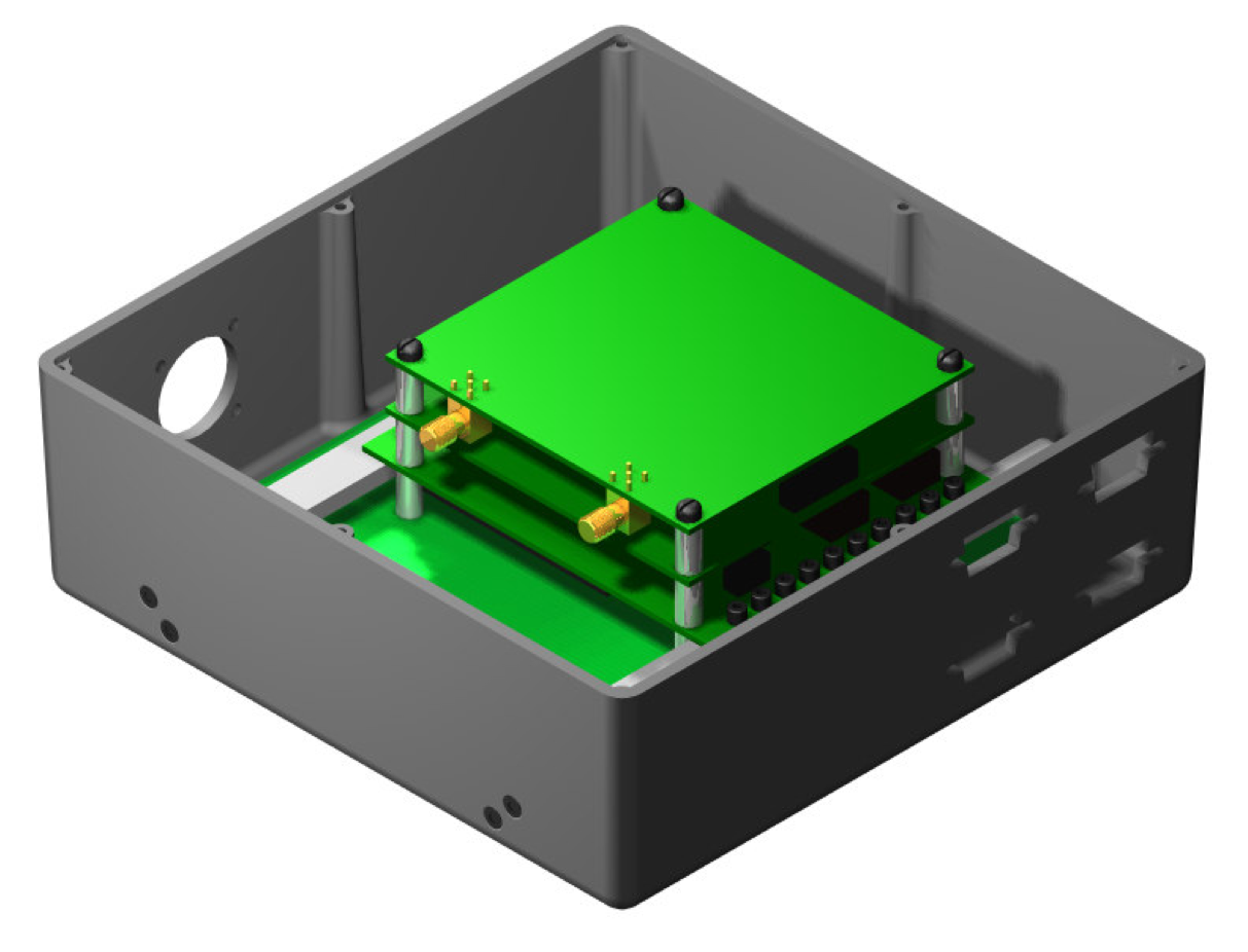
The following pdf shows how the PCB stack will be represented.
Media:IHU_ISO.pdf

Siren Revision A
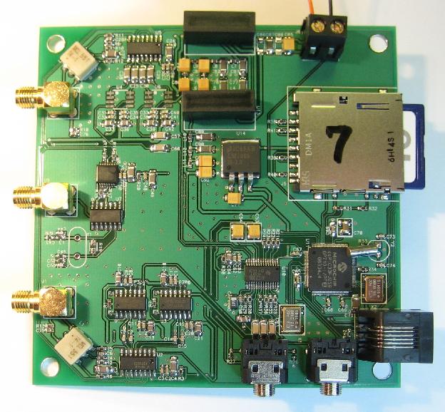
Siren - dsPIC33 based SDR tx/rx with seperate 10.7MHz input/output for external mixer/amplifier. Below are the Revision A of Siren schematics and PCB layout. The current design is based upon the the SDR1000 which was quick an easy to produce for testing and initial DSP programming. Revision B (see below) will have the newer designs for higher performance.
Features are: dsPIC33 TLV320AIC23B Codec QSD QSE crystal sampling clock optional SMA input for sampling clock
Media:SDX Schematic.pdf Proto 1 schematics
Media:SDX PCB.pdf PCB Layout
Odyssey Siren Revision A is RUNNING as a 10.7 MHz full duplex IF at 48 kHz bandwidth! We have FreeRTOS running on the board. The Siren dsPIC33 is running at the full 40 MIPS rate. Expect much more soon (2/3/2007).
Siren Revision B
This revision B schematic contains Ahti's OH2RZ ISD circuit and Howard Long's G6LVB exciter circuit (see STELLA [1]. The codec has been changed to the TLV320AIC31. The goal of the circuit is to take advantage of the differential inputs and outputs of the codec. --N7HPR 09:15, 30 October 2006 (PST)
Siren Revision C aka SDX This revision is the flight software defined transponder (SDX). The form factor has been reduced to better fit the satellite enclosure. Future designs may be cubesat sized (10cm x 10cm x 10cm).
Changes since Rev B include: 1) CPU is now a PIC32 to provide a 32-bit ALU, DMA and higher performance. 2) size has been reduced. 3) Input voltage is now 5v (from 12v) 4) Gain added to produce 0dbm at 10.7MHz. 5) filters added to remove 50kHz spurs.
Odysseus Rev A
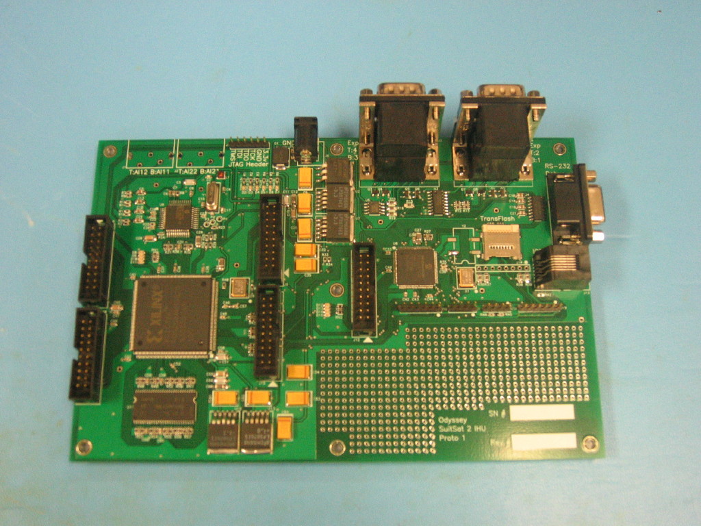
Odysseus - PIC24 based unit that will encode the SSTV, encode packet (with FX-25), and play recorded voice to the Siren board. The actual Flight hardware includes Cyclops, Odysseus, and Siren for a single IHU (Integrated Housekeeping Unit) The schematics below are the first prototype for the complete IHU.
Sheet 1 : (Cyclops) Wiring the CPLD. The CPLD steers the image data from the image capture chip into the DRAM. It also provides a DRAM interface for the PIC24 microcontroller. The CPLD adds the luminance data from the video feed so the PIC24 can get an idea if a bright object is in view. Any bright object seen by the Satellite is likely to be something interesting.
Sheet 2 : (Cyclops) This is the Philips SAA7113H video capture chip. This chip produces a stream of digital data representing an NTSC or PAL video feed. The digital data is stored into the CPLD.
Sheet 3 : This sheet contains the analog power supplies. The Video capture device and the CPLD/DRAM can be turned off to save power and extend the mission time. The final IHU will have an external switching regulator so this sheet will change. The LED's are for debugging the power management software.
Sheet 4 : (Cyclops) DRAM and terminating resistors.
Sheet 5 : (Odysseus) PIC24FJ128GA010 and interfaces. This is the 16 mips PIC24 microcontroller. It has 128kbytes of Flash. This device will be encoding the images for SSTV transmission, reading stored messages from the Transflash card, and collecting data from user supplied experiments. This microcontroller will produce digital audio data that will be sent to the siren baseband processor (a dsPIC33) via an SPI data bus. The flight hardware will have the siren integrated into the IHU motherboard.
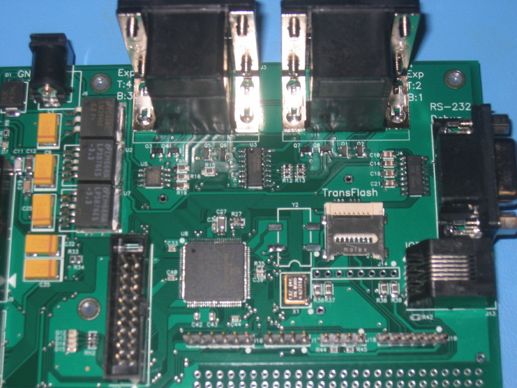
Sheet 6 : (Odysseus) This sheet has all the I/O for the transflash, the experiments and the serial debug port. It also has the prototype experiment power switch. The final power switch will be integrated into the external power supply. The experiment connector pinout will change. The current prototype shows the Rev 1 pinout. The Rev 2 pinout includes the video connections for the external cameras.
Schematics: Media:odysseus.pdf
Pictures IHU 


Software modules required are: SSTV Encoding (Scotty 1, Scotty 2, Robot 36) 1200 Baud Modem (transmitt only) AX-25/FX-25 Software Stack SD-Card Interface Power Management Mission Scheduler Uplink demodulator (unknown protocol)
Odysseus + Cyclops Flight Rev 1 aka IHU The original design was shrunk to a smaller form factor that will fit in the enclosure. Changes from Previous design include: 1) CPU changed from PIC24 to PIC32 (switch was driven by additional RAM required to buffer experiment data) DMA is an added benefit. 2) Excess connectors removed to allow a PCB shrink.
Media:IHU_Flight_V1_Schematic.pdf
Odysseus + Cyclops Flight Rev 2 aka IHU The previous flight candidate needed some additional adjustments. The design was getting tight in the Xilinx CPLD. Each compile iteration would randomly fit or fail to fit. Test compiles with an altera CPLD suggested that the design would perform better. Other changes include: 1) All serial ports moved to a single connector for debugging via the ICB. This simplified layout. 2) PIC32 pinout adjusted to make layout more efficient. 3) CPLD switched to Altera 4) 3.3v regulators switched to switchers (except for video capture IC) This reduces board heating. 5) PCB reduced in size again. This allows more room for wiring harness inside flight box. 6) Accelerometer removed. Math model suggested that no meaningful forces would be measurable. Media:IHU_V2A_Schematic.pdf Media:IHU_V2A_PCB.pdf
Cyclops
No progress has been made on this hardware. Cyclops - Video Capture for use by the Odysseus board.
Media:Odyssey Cyclops -ATLAS-.pdf
Media:Odyssey Cyclops -CPLD-.pdf
Media:Odyssey Cyclops -VIDEO-.pdf
Media:Odyssey Cyclops -POWER-.pdf
Media:Odyssey Cyclops -DRAM-.pdf
Media:Odyssey Cyclops -PCB-.pdf
Circe
Circe - mixer/amplifier for 2m tx and 70cm rx. This is the last piece for a complete satellite transponder. (Circe had a "split" personality)
PSU No clever Greek name has been suggested for the power supply unit but perhaps we should call it Icarus because we have 6 solar power converters on board. The PSU is a very small 25 watt power supply for the entire satellite. Features include: 1) 6 peak power trackers. Each power tracker has a PIC16F690 to monitor a single solar panel and wring the most power from each panel. 2) 8v switcher to power Circe. 3) 5v switcher for the electronics (switched to 3.3 on the other boards) 4) 12v boost from 5v for the cameras. 5) current sense on ALL loads and ALL switchers. This is for health monitoring 6) PIC16F887 to manage all supplies and report health status to the IHU via I2C. 7) I2C temperature sensor to monitor PCB heat levels. The biggest challenge is removing the heat. While this board only dissipates about 3 watts at full load, there is no convection in space so a standard heat sink is useless. The only choice is to conduct the heat to a larger radiator and remove the heat as black-body radiation. To aid this, a solid ground plane was used with many bolt tabs to attach this board to heat spreaders. The heat spreaders will conduct the heat to the system enclosure.
All design information is publicly available at https://svn.sarpeidon.net/suitsat2/
Feel free to look around.
